
LED (light-emitting diode) optical module for lighting, and LED chip

A technology of LED chips and optical modules, applied in lighting and heating equipment, components of lighting devices, cooling/heating devices of lighting devices, etc., can solve the problem of high cost

Active Publication Date: 2012-09-19
秦彪
View PDF4 Cites 4 Cited by
  • Summary
  • Abstract
  • Description
  • Claims
  • Application Information

AI Technical Summary

Problems solved by technology

It has been proposed to use high thermal conductivity ceramic sheets (such as AIN ceramic sheets) as the "heat sink" in the LED chip, which can solve the contradiction between insulation and heat transfer, but high thermal conductivity ceramics such as AIN are expensive.

Method used


Image

  • LED (light-emitting diode) optical module for lighting, and LED chip
  • LED (light-emitting diode) optical module for lighting, and LED chip
  • LED (light-emitting diode) optical module for lighting, and LED chip

Examples


Embodiment Construction

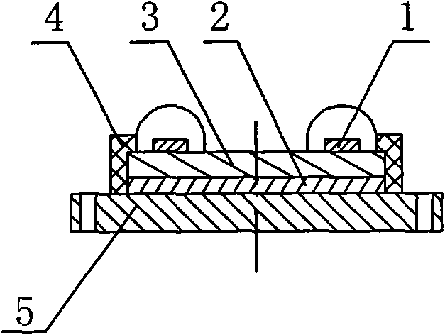
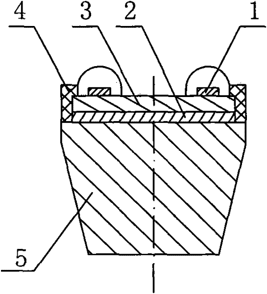
[0030] figure 1 In the shown LED light module of the present invention, the heat conduction core 5 is a flat plate structure, and is provided with mounting and fixing holes, and two LED chips 1 are shown in the figure. When there are multiple LED chips, attention should be paid to the design. The distribution of LED chips on the thermal diffusion plate should be radially dispersed. The power of a single LED chip should not be too large, preferably not more than 2 watts. The outer layer insulator 4 surrounds the edge sidewall of the thermal diffusion plate 3, and the outer layer insulator 4 extends to the high-voltage insulating sheet 2, and together with the high-voltage insulating sheet, the thermal diffusion plate is insulated from the heat-conducting core (and nearby conductors), thereby playing a role For high-voltage insulation, the insulation strength of the outer insulator should be higher than that of the high-voltage insulation sheet.

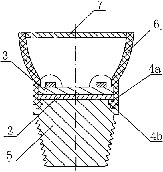
[0031] figure 2 The LED ligh...


PUM

PropertyMeasurementUnit
thicknessaaaaaaaaaa
thicknessaaaaaaaaaa
thermal conductivityaaaaaaaaaa

Abstract

The invention provides an LED (light-emitting diode) optical module and an LED chip. LED wafers (1) are arranged on a heat diffusion plate (3) which is made of copper, aluminum or copper-aluminum composite materials, the thickness of the heat diffusion plate is larger than 0.35mm, the area of the heat diffusion plate is more than five times of the total area of the LED wafers, and the purpose and the function of the heat diffusion plate is to reduce the heat-flow density; a high-voltage insulation sheet (2) bearing high-voltage insulation adopts a ceramic sheet such as aluminum oxide ceramic sheet, wherein the ceramic sheet is sintered into ceramic, is arranged at the other side of the heat diffusion plate (3) and insulates the heat diffusion plate together with an outer-layer insulation body (4). Injection or pouring process is adopted on the outer-layer insulation body, and THE outer-layer insulation body is formed together with the heat diffusion plate (3) and the high-voltage insulation sheet (2). The design can obviously reduce internal heat-conducting thermal resistance, improve the insulation strength of electricity and effectively lower the packaging cost.

Description

technical field [0001] The invention belongs to the technical field of LED lighting, and in particular relates to a packaging structure for reducing the internal thermal resistance of an LED light module or an LED chip and improving the insulation strength of the internal electricity. technical background [0002] One of the major applications of LED is lighting. LED lighting is considered to be the next generation of green and environmentally friendly lighting technology for human beings. However, the current high cost of LED lighting products hinders its popularization. The root cause of the high cost of LED lighting products is the heat dissipation of LEDs. The cost of the LED chip (also known as the bare chip) in the LED chip currently only accounts for 15%, and the packaging cost accounts for as much as 65%, which is caused by the problem of heat dissipation. [0003] The electrical safety of lighting fixtures is a requirement that must be met. It must meet the require...

Claims


Application Information

Patent Timeline
Patent Type & Authority Applications(China)
IPC IPC(8): F21S2/00F21V19/00F21V29/00H01L25/075H01L33/48H01L33/64F21Y101/02
CPCF21V3/00F21K9/00F21K9/90F21V29/246B29C45/14639F21K9/30B29C45/00F21Y2101/02F21K9/20F21K9/69F21V29/89F21Y2115/10
Inventor 秦彪
Owner 秦彪
Learn More