Seawater electromagnetic valve bank

A technology of solenoid valve group and solenoid valve, which is applied in the direction of valve details, valve device, valve operation/release device, etc., which can solve the problem of reducing anti-pollution ability and reliability, lack of precision filtration of water quality, and increasing the difficulty of processing parts and other problems, to achieve the effect of compact structure, quick response, convenient disassembly and maintenance

Active Publication Date: 2012-09-19
HUAZHONG UNIV OF SCI & TECH
View PDF5 Cites 7 Cited by
  • Summary
  • Abstract
  • Description
  • Claims
  • Application Information

AI Technical Summary

Problems solved by technology

[0005] (1) The flat valve structure is adopted, which has strict direction requirements for the water inlet and outlet, and cannot be reversed (that is, the inlet pressure of the valve is higher than the outlet, and the outlet is not higher than the inlet).
When the water inlet and outlet are connected reversely, even if the electromagnet is not activated, the medium pressure acts on the valve core to automatically open the valve port, resulting in misoperation;
[0006] (2) The structure is complex, and there are many small damping holes in principle, which not only increases the difficulty of processing parts, but also makes it difficult to assemble and maintain, and because the water quality in an open environment cannot be filtered precisely, it is easy to cause damping holes Blockage, which reduces the pollution resistance and reliability of the valve;
[0008] (4) Guide the inlet pressure to the end of the main valve core, and rely on the pressure to increase the sealing specific pressure at the valve port, so it is easy to cause the valve port to be closed tightly at low pressure, and there is a large leakage;

Method used


Image

  • Seawater electromagnetic valve bank
  • Seawater electromagnetic valve bank
  • Seawater electromagnetic valve bank

Examples


Embodiment Construction

[0032] The present invention will be further described below in conjunction with the accompanying drawings and embodiments.

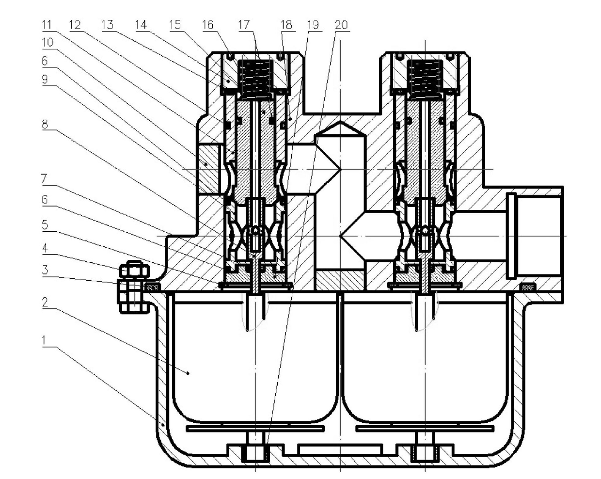
[0033] The seawater solenoid valve group in this embodiment is integrated by four independent solenoid valves. image 3 A schematic diagram of the internal structure of the solenoid valve group is given. Each solenoid valve includes a valve assembly, an electromagnet assembly 2 and a sealing cover 1 . Each solenoid valve body 18 is combined with the sealing cover 1 through 12 bolts, nuts, elastic washers and flat washers 4, and an O-ring 3 is added to realize sealing.

[0034] The valve assembly part of each solenoid valve includes a valve body 18, a screw plug 14, a spring 16, a valve core 15, a valve sleeve 11, a valve seat 9, a push rod 8, a valve sleeve seat 19, a retaining ring 5 and seals, electric- The mechanical conversion device includes a moving iron core 26, a pole shoe 22, a push rod 27, a rubber sleeve 25, a coil 24, a guide copper sleeve...


PUM


Abstract

The invention discloses a seawater electromagnetic valve bank, which consists of four mutually independent electromagnetic valves, wherein each electromagnetic valve comprises a valve component and an electromagnet component which is arranged below the valve component; each valve component comprises a valve body and a valve core which is arranged in the valve body; each electromagnet component isaccommodated in a sealing cover; each sealing cover is fixedly connected with each valve body into a whole; a valve sleeve is arranged outside each valve core; the lower part of each valve core is provided with a valve seat; each valve core and the corresponding valve seat form a valve port; the lower part of each valve seat is provided with a valve sleeve seat; one end of a push rod penetrates through each valve sleeve seat and then comes into contact with the lower part of the corresponding valve core, and the other end of the push rod is in contact with the corresponding electromagnet component; the upper part of each valve core is sealed through a screw plug; the top of each valve core is butted against the corresponding screw plug through a spring; and a stop ring is arranged at the position of the lower part of each valve sleeve seat, between each valve component and the corresponding electromagnet component. The valve bank provided by the invention can be directly applied to seawater environments and other corrosive environments, and has the advantages of simple structure, small pressure loss, convenience in disassembly, assembly and maintenance, no small damping holes, high anti-pollution capacity and the like.

Description

technical field [0001] The invention relates to a seawater solenoid valve group, which is suitable for a water pressure buoyancy adjustment system of an underwater submersible and other systems using seawater, fresh water and other working media. technical background [0002] The seawater hydraulic components involved in the seawater buoyancy adjustment system include seawater pumps, seawater solenoid valves, seawater overflow valves, and seawater pressure balance valves. Its system principle is as figure 1 As shown, the seawater solenoid valve is an important part of the seawater hydraulic buoyancy adjustment system, and is a transportation hub for controlling the seawater injection or discharge system. By adjusting the on-off state of the solenoid valve group, injecting or discharging seawater into the water tank of the deep submersible to change the weight of the submersible, thereby changing the buoyancy of the submersible and the specific gravity of the weight, thereby...

Claims


Application Information

Patent Timeline
Patent Type & Authority Applications(China)
IPC IPC(8): F16K31/06
Inventor 刘银水毛旭耀江涛李东林吴德发杨珍赵旭峰方无迪
Owner HUAZHONG UNIV OF SCI & TECH
Why Eureka
Try Eureka