
Light emitting diode (LED) narrow beam floodlight

A floodlight and narrow beam technology, which is applied in the field of energy-saving LED lamps, can solve the problems of difficulty in highlighting the layered effect of the illuminated surface, insufficient concentration of light intensity distribution, and easy fatigue of the human eye, achieving good lighting effect, large illuminated surface, and bright light. The effect of strong distribution concentration

Inactive Publication Date: 2012-09-12
DONGGUAN JIA SHENG LIGHTING TECH CO LIMTED
View PDF5 Cites 2 Cited by
  • Summary
  • Abstract
  • Description
  • Claims
  • Application Information

AI Technical Summary

Problems solved by technology

When used for lighting, the projection distance of light is often relatively short. Using the existing LED floodlights will produce the effect that the illuminated surface is small and too bright, and the surrounding environment is too dark, which makes human eyes easy to fatigue; when used for decoration, the current Some LED floodlights have insufficient distribution of light intensity, making it difficult to highlight the layered effect of the illuminated surface

Method used


Image

  • Light emitting diode (LED) narrow beam floodlight
  • Light emitting diode (LED) narrow beam floodlight
  • Light emitting diode (LED) narrow beam floodlight

Examples


Embodiment

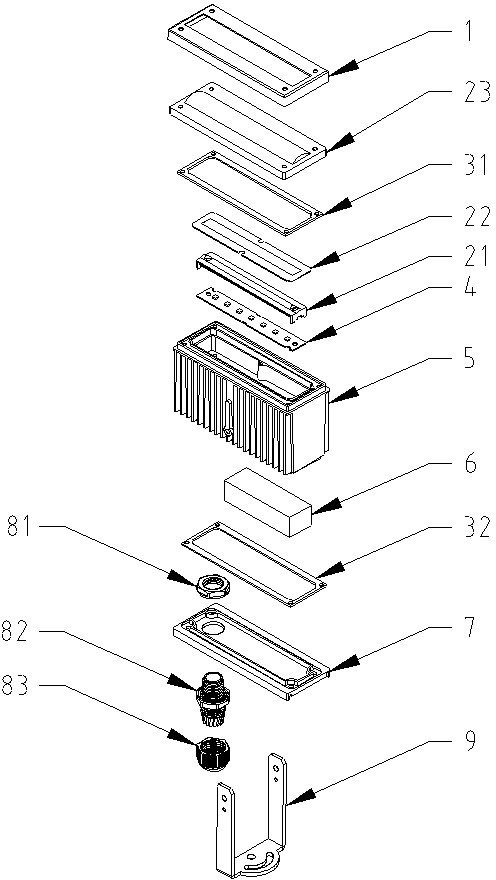
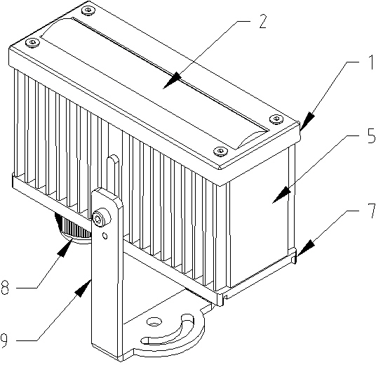
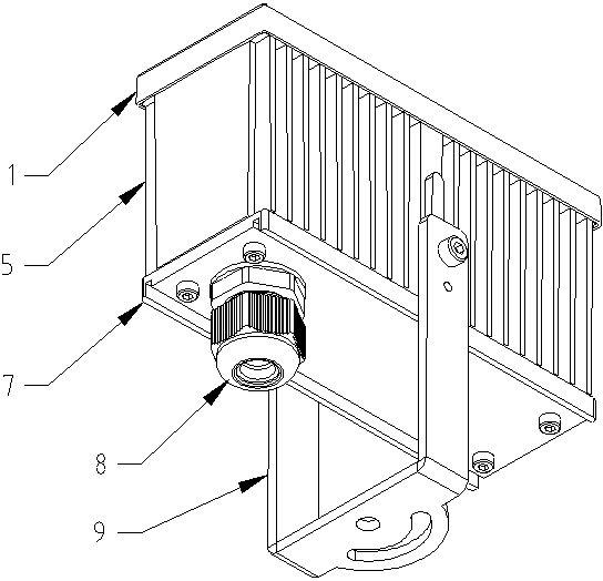
[0027] The ED narrow-beam projection lamp of the present invention is respectively as follows Figure 1 to Figure 8 As shown, the LED narrow-beam floodlight of the present invention includes an upper cover 1, an optical lens group 2, an LED module 4, a housing 5, a driver 6, and a lower cover 7, wherein the lower cover 7 is installed on the housing 5 The bottom of the bottom, the driver 6 and the LED module 4 are placed in the hollow cavity provided by the housing 5 and supported on the housing 5, and the LED module 4 is electrically connected to the driver 6, and the optical lens group 2 is placed in the LED module 4, the upper cover 1 is installed on the top of the housing 5 to fix the optical lens group 2.

[0028] In this embodiment, an electrical connector 8 is installed on the lower cover 7 , and the driver 6 is connected to a power source through the electrical connector 8 .

[0029] In addition, a lower waterproof ring 32 is installed between the housing 5 and the low...


PUM


Abstract

The invention relates to a light emitting diode (LED) narrow beam floodlight, which comprises an upper cover (1), an optical lens group (2), an LED module (4), a shell (5), a driver (6) and a lower cover (7). The lower cover (7) is arranged at the bottom of the shell (5). The driver (6) and the LED module (4) are arranged in a hollow chamber of the shell (5) and supported on the shell (5). The LED module (4) is electrically connected with the driver (6). The optical lens group (2) is arranged above the LED module (4). The upper cover (1) is installed on the top of the shell (5) and the optical lens group (2) is fixed. The LED narrow beam floodlight is applicable for lighting decoration and lighting in places such as walls, columns and footpath ground, and the lighting area is controlled without affecting surroundings. When used for lighting, the floodlight can be horizontally installed, the horizontal half-peak illuminance angle of a beam is increased to be more than 55 degrees, light distribution is uniform and a lighting area is large; when used for decoration, the longitudinal half-peak illuminance angle is reduced to be within 10 degrees, light distribution is concentrated and a hierarchical effect is good.

Description

technical field [0001] The invention belongs to a lamp in the field of electrical lighting, and in particular relates to an energy-saving LED lamp that needs to control the illuminated surface of the light without affecting the surrounding environment. Background technique [0002] As a high-efficiency and energy-saving light-emitting element, LED is currently widely used in various decorations and lighting fixtures. Due to the limitation of the LED structure, the light beam emitted by it is mainly concentrated in the forward direction, and the 1 / 2 illumination angle is in the circular range of about 45°. [0003] Existing LED floodlights mainly use circularly distributed LED modules, and use secondary optical lenses alone to concentrate the light beams within a circle with a 1 / 2 illumination angle of about 16°, such as Figure 9 shown. When used for lighting, the projection distance of light is often relatively short. Using the existing LED floodlights will produce the eff...

Claims


Application Information

Patent Timeline
Patent Type & Authority Applications(China)
IPC IPC(8): F21S8/00F21V17/00F21V31/00F21V5/04F21V29/00F21Y101/02F21V29/507F21V29/76F21Y115/10
Inventor 徐志君陈益民
Owner DONGGUAN JIA SHENG LIGHTING TECH CO LIMTED
Learn More