Eureka AIR delivers breakthrough ideas for toughest innovation challenges, trusted by R&D personnel around the world.

Light source module and display apparatus having the same

a technology of light source module and display apparatus, which is applied in the direction of instruments, discharge tubes luminescnet screens, lighting and heating apparatus, etc., can solve the problems of low color reproducibility of display panel, unfavorable color coordinate change, and difficulty in developing light source color reproducibility and good light efficiency, so as to achieve stable light efficiency and enhance color reproducibility

Active Publication Date: 2012-11-06
SAMSUNG DISPLAY CO LTD
View PDF11 Cites 36 Cited by
  • Summary
  • Abstract
  • Description
  • Claims
  • Application Information

AI Technical Summary

Benefits of technology

[0009]Exemplary embodiments of the present invention provide a light source module having stable light efficiency and high color reproducibility using a small number of light-emitting diodes (LEDs).
[0010]Exemplary embodiments of the present invention also provide a display apparatus having high color reproducibility.
[0019]According to exemplary embodiments of the present invention, each of the variations of amounts of red, green and blue light is very small even though the variation of a temperature is very large, so that stable light efficiency may be obtained. Thus, expensive technology such as a color feedback system may be unnecessary and color reproducibility may be enhanced.

Problems solved by technology

One challenge in using LEDs as a backlight light source is to produce a white light, as LEDs tend to be monochromatic.
However, the above-mentioned blue LED chip merely uses blue and yellow light to emit the white light without using full colors having red, green and blue light, and thus color reproducibility of the display panel is decreased.
Research has been conducted to enhance color reproducibility in LED backlights, but a light source having good color reproducibility and good light efficiency has not been easy to develop.
Because temperature can affect a red, blue and green LED differently, changes in temperature may result in undesirable changes in color coordinates.
In addition, the number of LEDs used and costs due to the feedback system may be relatively high.

Method used


Image

  • Light source module and display apparatus having the same
  • Light source module and display apparatus having the same
  • Light source module and display apparatus having the same

Examples


Embodiment Construction

[0032]Exemplary embodiments of the present invention are described more fully hereinafter with reference to the accompanying drawings. The present invention may, however, be embodied in many different forms and should not be construed as limited to the exemplary embodiments set forth herein. In the drawings, the sizes and relative sizes of layers and regions may be exaggerated for clarity.

[0033]It will be understood that when an element or layer is referred to as being “on,”“connected to” or “coupled to” another element or layer, it can be directly on, connected or coupled to the other element or layer or intervening elements or layers may be present.

[0034]Hereinafter, exemplary embodiments of the present invention will be explained in detail with reference to the accompanying drawings.

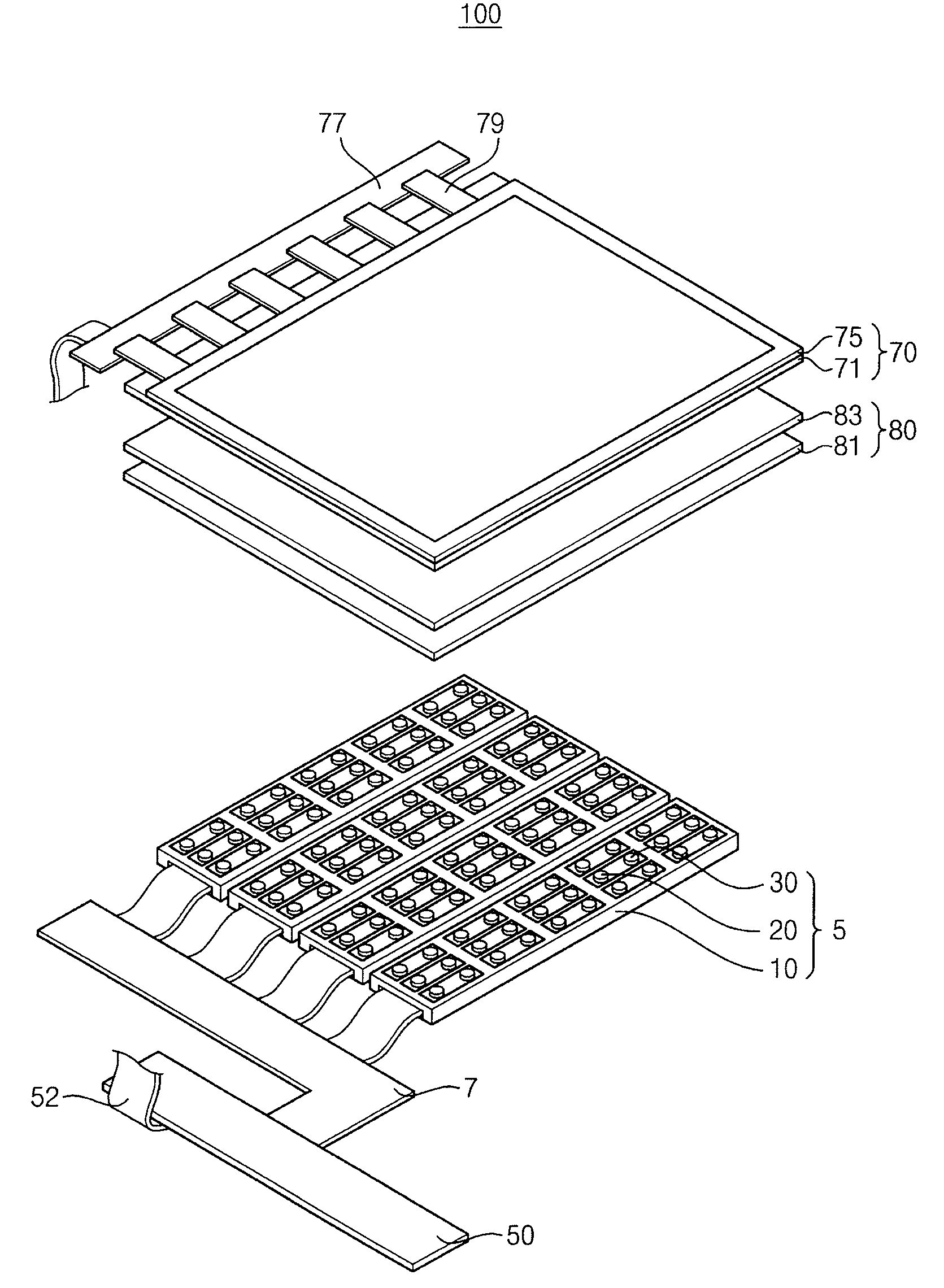
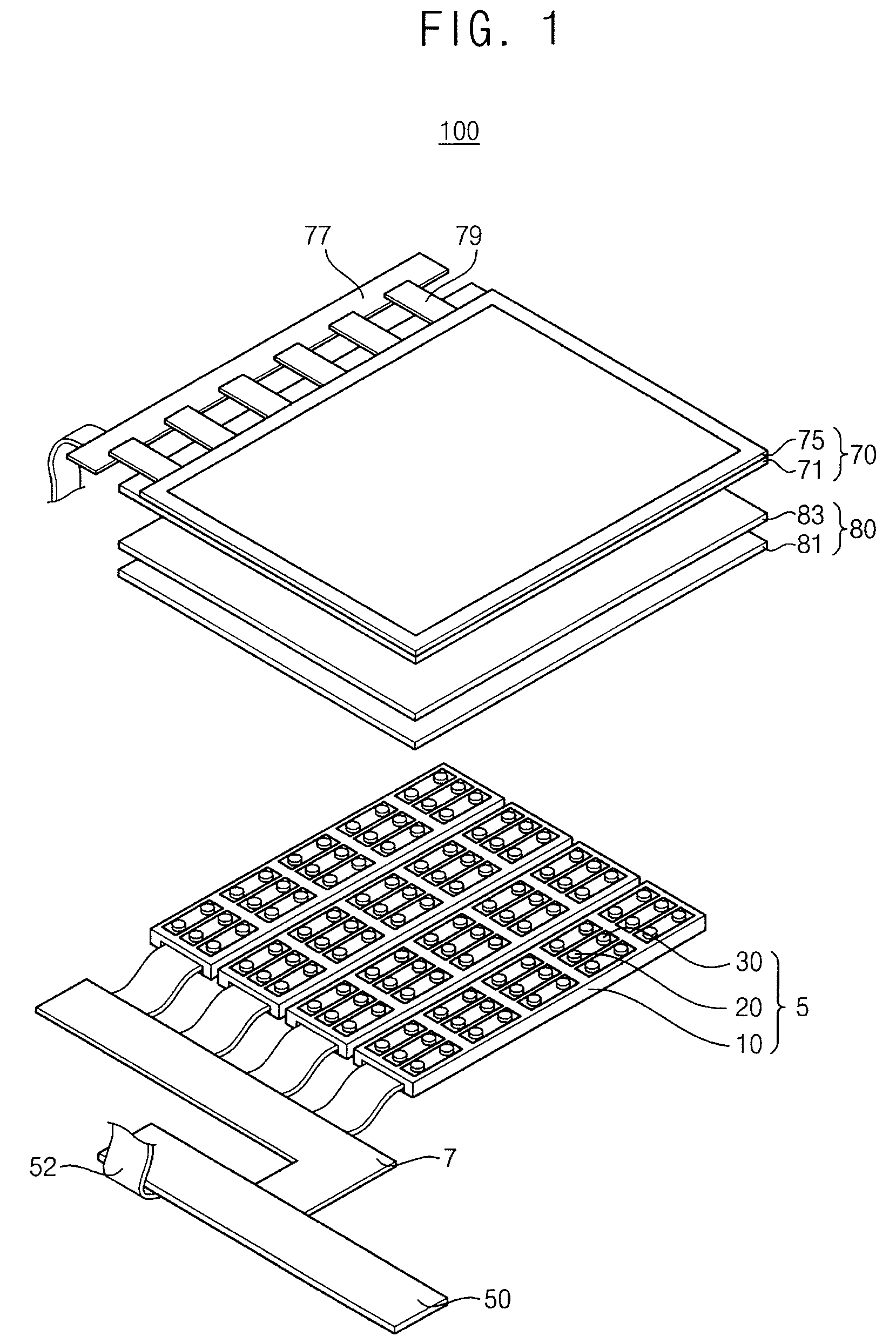
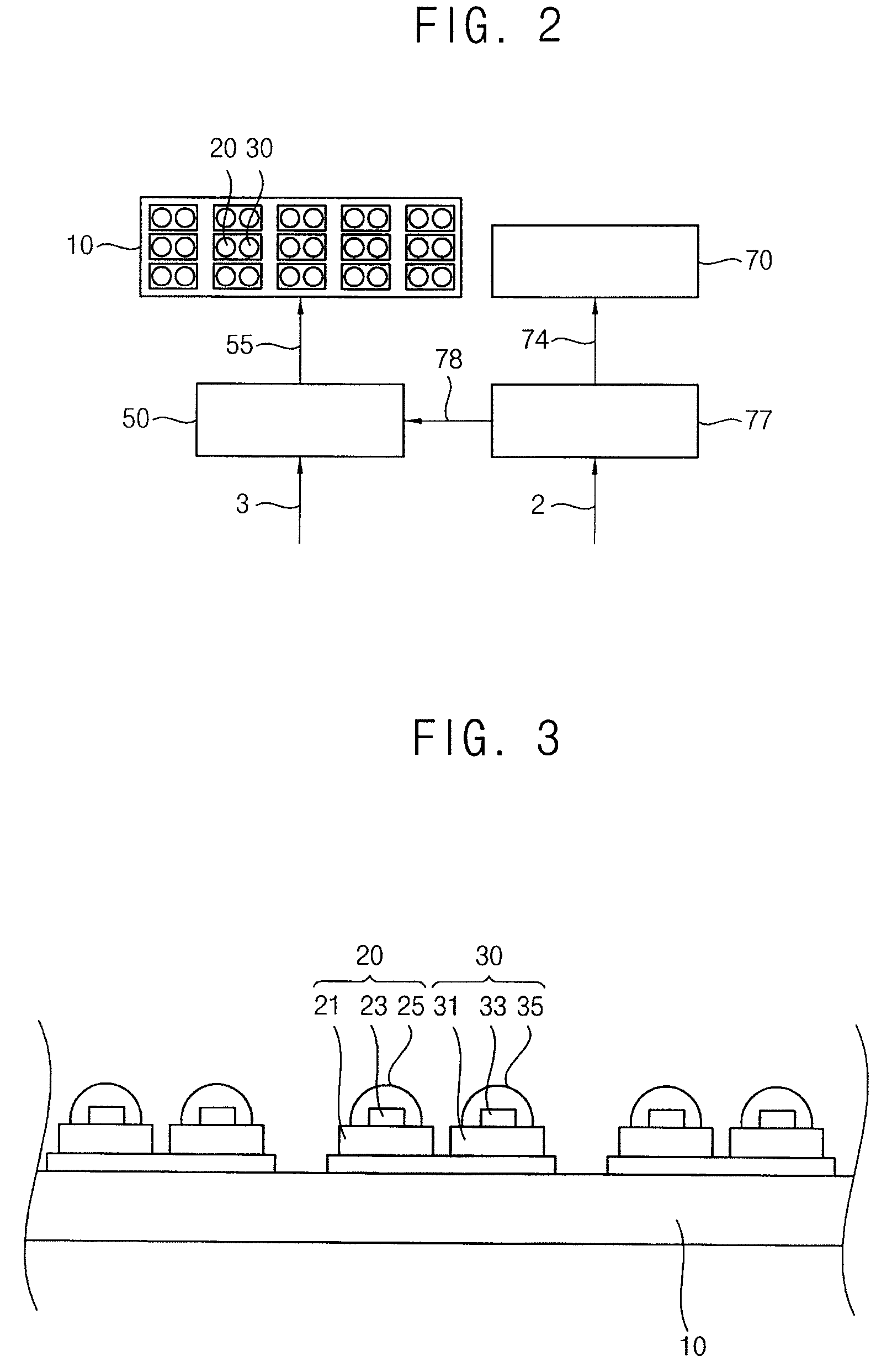
[0035]FIG. 1 is an exploded perspective view illustrating a display apparatus according to an exemplary embodiment of the present invention. FIG. 2 is a block diagram illustrating the display apparatu...


PUM


Abstract

A light source module includes first and second light sources. The first light source includes a blue light-emitting body emitting blue light and a red fluorescent material disposed around the blue light-emitting body emitting red light by virtue of being excited by the blue light. The second light source is disposed adjacent to the first light source, and includes a green light-emitting body emitting green light. The blue and green light-emitting materials may include a light-emitting diode (LED) chip including substantially the same material. Accordingly, since a variation of light efficiency of the light source module with respect to temperature is small, a color feedback system may be omitted, and color reproducibility may be high.

Description

CROSS-REFERENCE TO RELATED APPLICATIONS[0001]This application claims priority under 35 U.S.C. §119 to Korean Patent Application No. 10-2008-0089836, filed on Sep. 11, 2008 in the Korean Intellectual Property Office (KIPO), the contents of which are herein incorporated by reference in their entirety.BACKGROUND OF THE INVENTION[0002]1. Technical Field[0003]The present invention relates to a light source module and more particularly, the present invention relates to a light source module and a display apparatus having the light source module.[0004]2. Discussion of the Related Art[0005]Generally, a liquid crystal display (LCD) apparatus includes a backlight assembly providing light to a display panel to display an image. A cold cathode fluorescent lamp (CCFL) is often used as a light source of the backlight assembly. More recently, light-emitting diodes (LEDs) have been used as a light source because the LED has low power consumption, small volume and light weight.[0006]One challenge in...

Claims


Application Information

Patent Timeline
Patent Type & Authority Patents(United States)
IPC IPC(8): H01L33/00G09G3/36F21V9/40
CPCC09K11/592C09K11/595G02F1/133603G02F1/1335
Inventor KIM, HYUN-JINNAM, SEOK-HYUNLEE, DONG-CHINKIM, HYUK-HWANWANG, MIN-JEONG
Owner SAMSUNG DISPLAY CO LTD
Why Eureka
Eureka Blog
Learn More