
Cyanide leaching device for gold ore

A technology for cyanide leaching and gold mines, which is applied in the field of mining and metallurgical engineering, can solve the problems of limited suction speed, large space occupation, inability to meet the oxygen consumption of gold electrochemical reaction and adsorption oxygen consumption, etc., to achieve enhanced cyanide The effect of chemical leaching process and improving leaching rate

Inactive Publication Date: 2012-09-12
CHANGAN UNIV
View PDF0 Cites 8 Cited by
  • Summary
  • Abstract
  • Description
  • Claims
  • Application Information

AI Technical Summary

Problems solved by technology

[0003] The mechanical stirring leaching tank can only generate negative pressure and suction when the stirring paddle rotates at high speed, so the suction volume will be limited by the speed
Practice has shown that the air intake of the mechanically stirred leaching tank cannot meet the oxygen consumption of the electrochemical reaction and adsorption of gold, and the leaching process is always in a state of oxygen supply starvation.
[0004] In the mechanical stirring leaching tank, the rotation of the impeller and the shape of the bottom of the leaching tank also have a certain influence on the optimal oxygen supply mode. The bottom of the traditional stirring leaching tank is easy to form a dead zone, which is not conducive to cyanide leaching
[0005] Although the air-stirred leaching tank can make the oxygen content in the pulp close to the saturation value, it takes up a lot of space, requires a lot of investment, and consumes a lot of power. It is suitable for cyanide leaching that requires strong stirring and a large amount of aeration.
[0006] The filling of air in the stirring tank changes the specific gravity of local pulp, increases the power consumption of mechanical stirring, and makes a lot of power loss in the formation of pulp vortex and mechanical wear, so the energy efficiency is low

Method used


Image

  • Cyanide leaching device for gold ore
  • Cyanide leaching device for gold ore
  • Cyanide leaching device for gold ore

Examples


Embodiment Construction

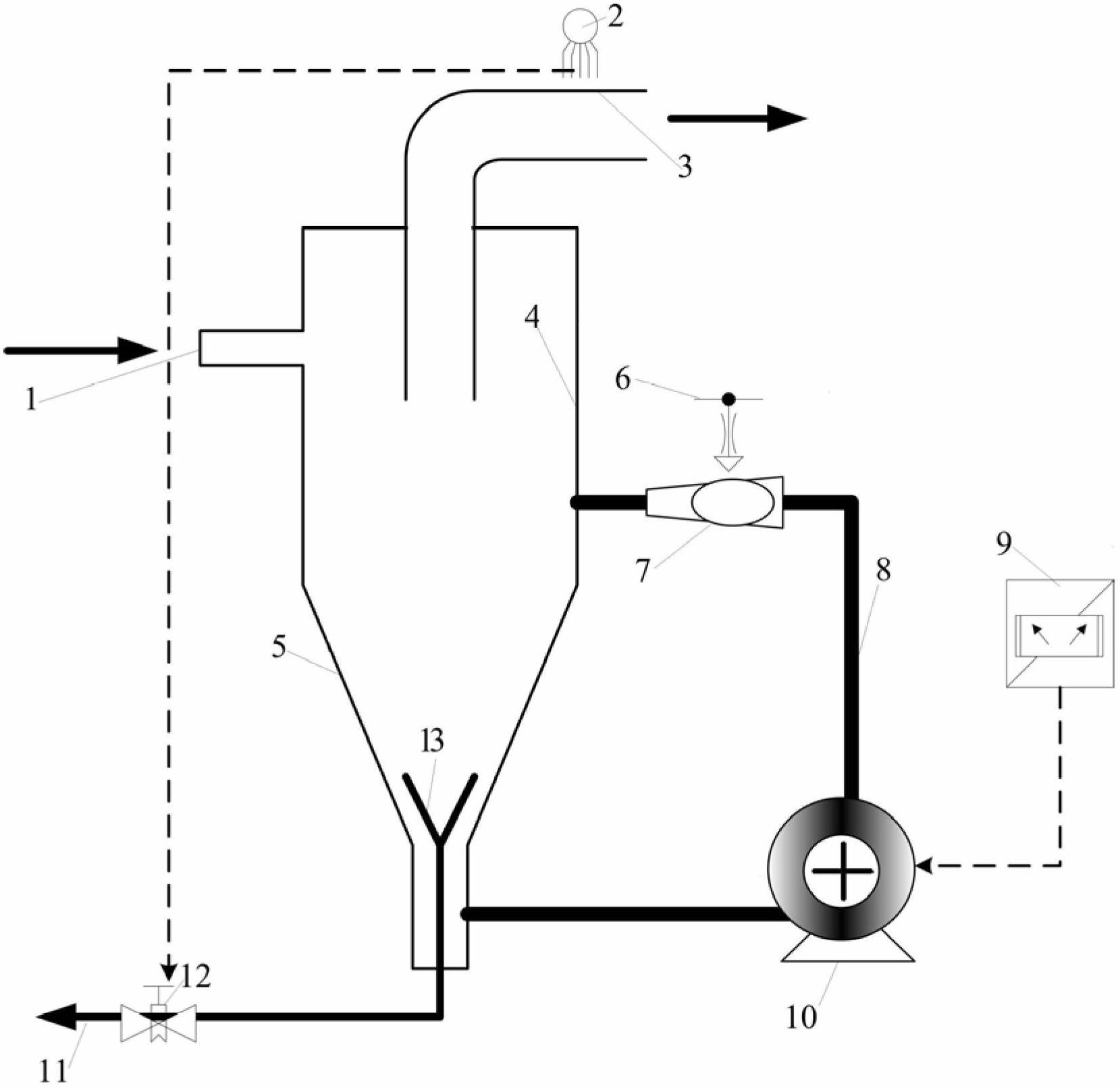
[0022] The present invention will be described in further detail below in conjunction with the accompanying drawings.

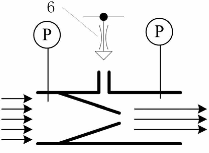
[0023] see figure 2 , 3, 4, the present invention comprises the cyclone leaching column that the upper end is a cylinder 4, the lower end is a cone 5, and the top and side walls of the cylinder 4 are respectively provided with an overflow ore discharge port 3 and an ore feed port 1, The ore inlet 1 is tangent to the cylinder 4, the lower end of the cone 5 is provided with a separation bottom cone 13, and the lower end of the separation bottom cone 13 is connected to the sand discharge outlet 11, and the cavity formed by the separation bottom cone 13 and the inner wall of the cone 5 The pipeline is connected to the circulation pump 10, the circulation pipeline 8, and the bubble generator 7 in turn. The outlet of the bubble generator 7 is connected to the cylinder 4 through the through hole on the side wall of the cylinder 4. The bubble generator 7 passes thro...


PUM


Abstract

The invention discloses a cyanide leaching device for gold ore. For overcoming the defects of small aeration quantity, dead zone existence, low leaching rate and high energy consumption in the currently-used agitation leaching groove, a leaching column is novel leaching equipment for combining cyclone separation with pipe flow strengthened leaching and achieving dual goals of grading and leaching in one equipment. According to the cyanide leaching device disclosed by the invention, the inspiratory capacity is increased and the turbulence level of gas, liquid and solid phases is improved by a bubble generator adopting a jet principle, so that the full air amount can be ensured and enough stirring strength is ensured. According to the pipe flow cycle intensifying leaching mode for a coarse fraction refractory leaching gold grain intergrowth body, strong pertinence is realized, the leaching rate of gold ore can be effectively increased and the cyanide leaching process of the gold ore is intensified.

Description

technical field [0001] The invention belongs to the technical field of mining and metallurgical engineering, and relates to equipment used in chemical mineral dressing and hydrometallurgy, in particular to a gold ore cyanide leaching device. Background technique [0002] Cyanidation is the most widely used production process in gold mines. At present, most of the cyanide leaching operations in my country's gold mines use mechanical agitation leaching tanks, and only a few enterprises use air agitation leaching tanks and combined air and mechanical agitation leaching tanks. [0003] The mechanical stirring leaching tank can only generate negative pressure and suck air when the stirring paddle rotates at high speed, so the suction volume will be limited by the rotating speed. Practice has shown that the air intake of the mechanically stirred leaching tank cannot meet the oxygen consumption of the electrochemical reaction and adsorption of gold, and the leaching process is alw...

Claims


Application Information

Patent Timeline
IPC IPC(8): C22B3/02C22B3/04C22B11/08
CPCY02P10/20
Inventor 郑贵山杨兴科
Owner CHANGAN UNIV
Learn More