Eureka AIR delivers breakthrough ideas for toughest innovation challenges, trusted by R&D personnel around the world.

Load-controllable multichannel liquid fuel gasification burner

A liquid fuel, controllable technology, applied in the direction of inorganic chemistry, chemical instruments and methods, non-metallic elements, etc., can solve the problems of poor atomization performance, difficult load control, poor burner cooling effect, etc., to achieve improved fog Excellent atomization performance, convenient production and maintenance, and sufficient atomization effect

Active Publication Date: 2014-05-14
SHANGHAI BOILER WORKS
View PDF9 Cites 0 Cited by
  • Summary
  • Abstract
  • Description
  • Claims
  • Application Information

AI Technical Summary

Problems solved by technology

[0006] The technical problem to be solved by the present invention is to provide a load-controllable multi-channel liquid fuel gas burner technology in order to overcome the shortcomings of the prior art gasification burner technology, such as difficult load regulation, poor burner cooling effect and poor atomization performance. chemical burner

Method used


Image

  • Load-controllable multichannel liquid fuel gasification burner
  • Load-controllable multichannel liquid fuel gasification burner
  • Load-controllable multichannel liquid fuel gasification burner

Examples


Embodiment 1

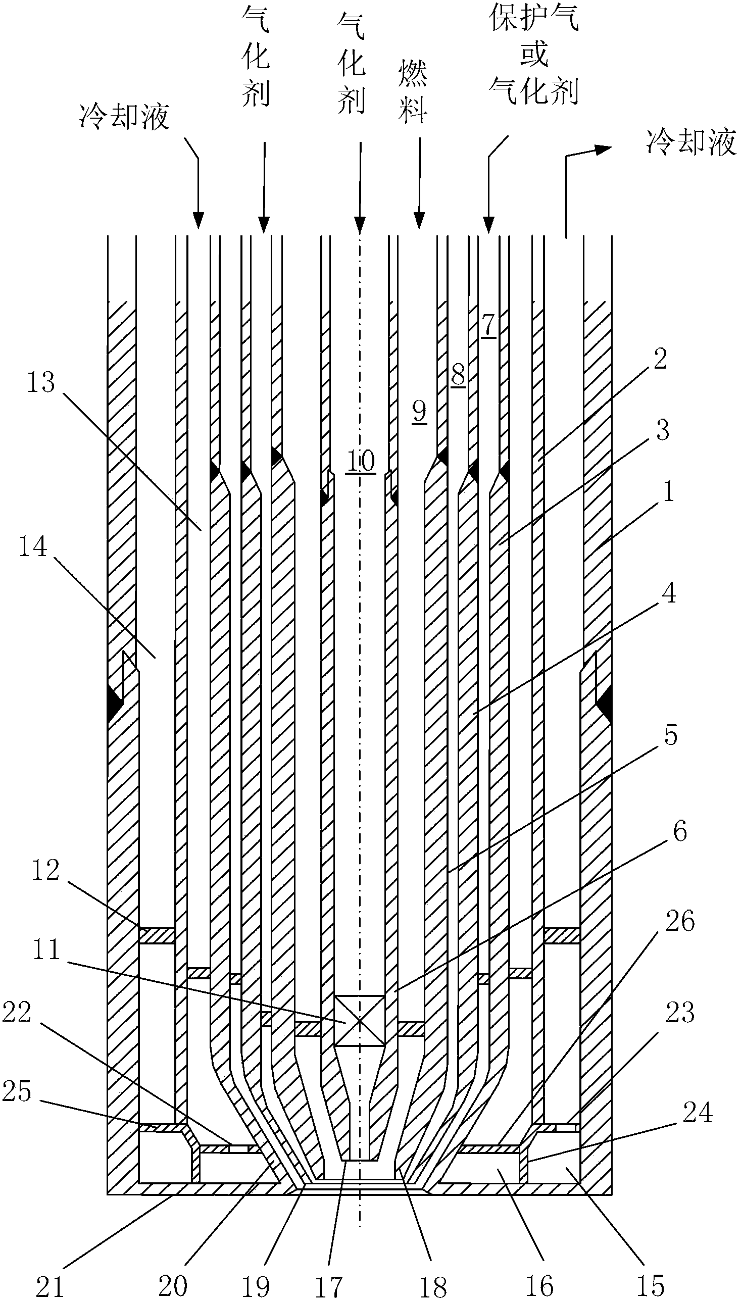
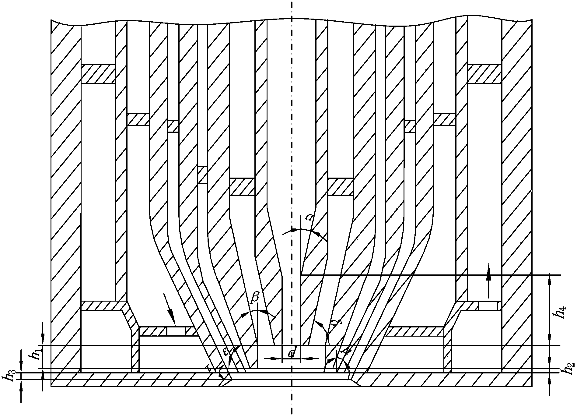
[0044] Figure 1~3 It is a schematic diagram of the peripheral structure and internal structure of the load controllable multi-channel liquid fuel gasification burner of the present invention. The burner includes a protective purge gas inlet 29, a central oxidant inlet 30, a fuel inlet 31, an outer ring channel oxidant inlet 32, an outer ring oxidant or protective gas inlet 33, a coolant inlet 34, a coolant outlet 35, and a connection method Lan 36, the coaxial burner center nozzle 6, the first burner outer ring nozzle 5, the second burner outer ring nozzle 4, the third burner outer ring nozzle 3 and the burner center nozzle 17, the second A burner outer ring nozzle 18, a second burner outer ring nozzle 19, a third burner outer ring nozzle 20, a cyclone 11 and a burner cooling system.

[0045] Said burner center nozzle 17, first burner outer ring nozzle 18, second burner outer ring nozzle 19 and third burner outer ring nozzle 20 are respectively a truncated conical tube. The...

Embodiment 2

[0059] The difference between this embodiment and Embodiment 1 is that if the burner is installed in a single-nozzle overhead coal-water slurry gasifier, when the fuel is oil coke slurry with a concentration of 65%wt, the gas will be burned with 98% pure oxygen It is the gasification agent, and the gasification result is the effective gas components CO and H in the syngas 2 The sum of the volume percentage of the burner reaches 86%, the residual carbon of the ash residue is 4%, and the continuous service life of the burner can reach 5 months, which fully meets the requirements of the gasification of oil coke slurry.

[0060] Said burner structure parameters are as follows:

[0061] β is 15°, ε is 60°; β is 20°, ε is 45°; μ is 30°; τ is 60°. The nozzle diameter d of the nozzle 17 in the center of the burner and the height h of the straight section of the nozzle 4 The ratio of h 4 :d=3. The distance h between the nozzle end face of the burner center nozzle 17 and the nozzle ...


PUM

PropertyMeasurementUnit
heightaaaaaaaaaa
thicknessaaaaaaaaaa

Abstract

The invention discloses a load-controllable multichannel liquid fuel gasification burner, which comprises a burner central spray pipe, a first burner outer ring spray pipe, a second burner outer ring spray pipe, a third burner outer ring spray pipe, a burner central sprayer, a first burner outer ring sprayer, a second burner outer ring sprayer, a third burner outer ring sprayer, a swirler and a burner cooling system, wherein the burner central spray pipe, the first burner outer ring spray pipe, the second burner outer ring spray pipe and the third burner outer ring spray pipe are coaxial. According to the load-controllable multichannel liquid fuel gasification burner disclosed by the invention, the rotation of airflow in a central channel is enhanced by adopting a multichannel structural design through arranging the swirler in a central channel spray pipe, thus, the overall atomization performance of the burner is improved. By adopting the multichannel design, on one hand, the atomization of the airflow to liquid fuel can be enhanced, and on the other hand, the regulation on the flow of a gasification agent and the flow of the liquid fuel can be enhanced, thus, the load of the gasification burner is effectively regulated. The liquid fuel burner is cooled by adopting a jacket-type cooling mode. Compared with a coiled pipe-type cooling effect of a traditional industrially applied liquid fuel gasification burner, the jacket-type cooling effect is obviously enhanced.

Description

technical field [0001] The invention relates to a liquid fuel gasification burner, in particular to a load controllable multi-channel liquid fuel gasification burner. Background technique [0002] The clean and efficient utilization of coal and other carbon-containing fuels has gradually become an important issue in today's energy utilization. Fuel gasification to syngas can provide leading technologies for modern chemical production, combined cycle power generation (IGCC power generation for short), indirect coal liquefaction, and coal-to-hydrogen systems. At present, the gasification technology of coal and other carbon-containing fuels to produce syngas is generally divided into two categories, one is liquid fuel gasification technology, and the other is dry powder solid fuel gasification technology. As one of the key components of gasification, the development of burner technology directly determines the operation stability and reliability of liquid fuel gasification tec...

Claims


Application Information

Patent Timeline
Patent Type & Authority Patents(China)
IPC IPC(8): C01B3/32
Inventor 倪建军乌晓江张建文熊杰
Owner SHANGHAI BOILER WORKS
Why Eureka
Eureka Blog
Learn More