
Laser machining equipment

A laser processing and equipment technology, which is applied in the field of laser processing equipment for processing light guide plates, can solve the problems of poor light guide effect, low production efficiency, and long processing time, so as to improve processing quality and processing accuracy, facilitate operation, and process Guaranteed effect

Active Publication Date: 2012-08-29
GUANGDONG HANS YUEMING LASER GRP CO LTD
View PDF8 Cites 15 Cited by
  • Summary
  • Abstract
  • Description
  • Claims
  • Application Information

AI Technical Summary

Problems solved by technology

The disadvantages of using bitmap (or vector filling map) engraving are mainly that the processing time is long and the production efficiency is too low, but the light guide effect is not good when using the scribing method

Method used


Image

  • Laser machining equipment
  • Laser machining equipment
  • Laser machining equipment

Examples


Embodiment Construction

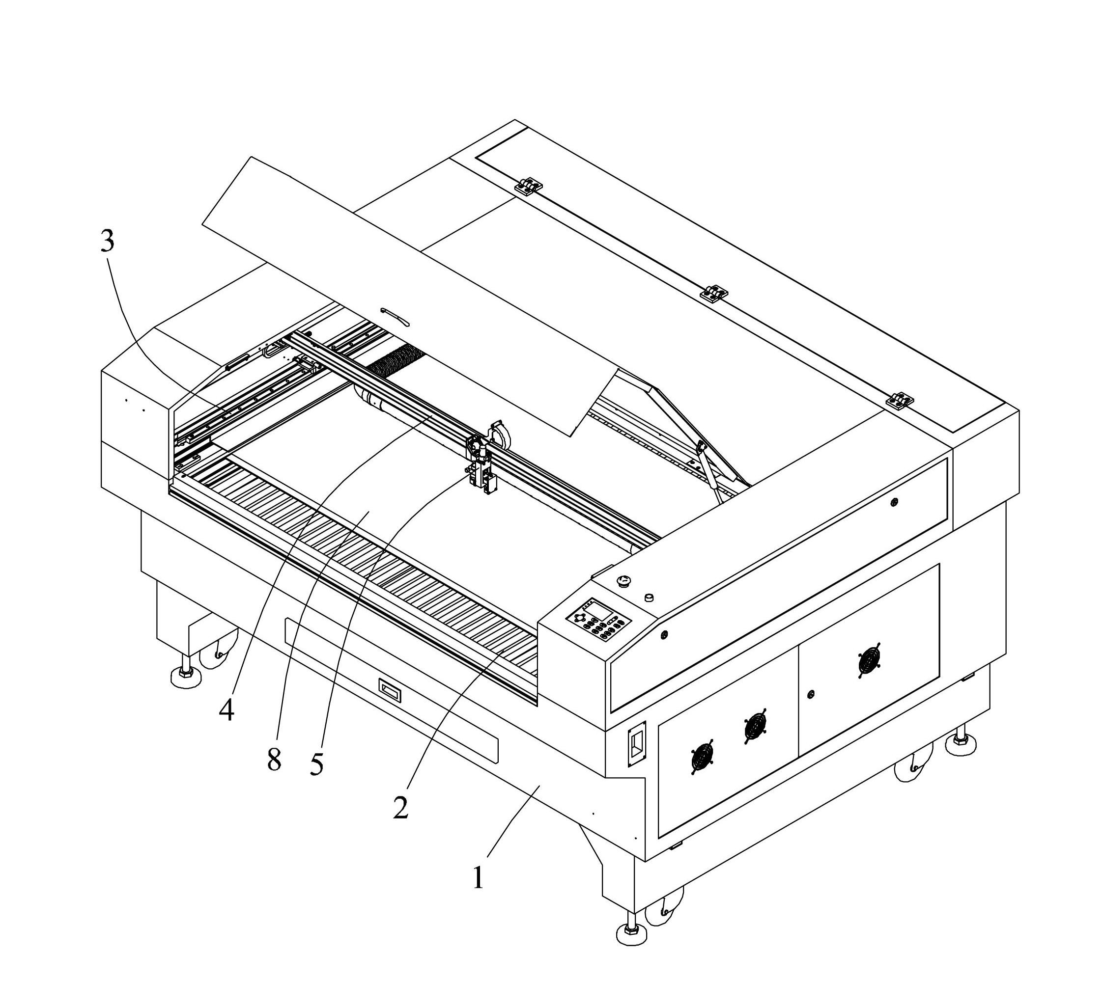
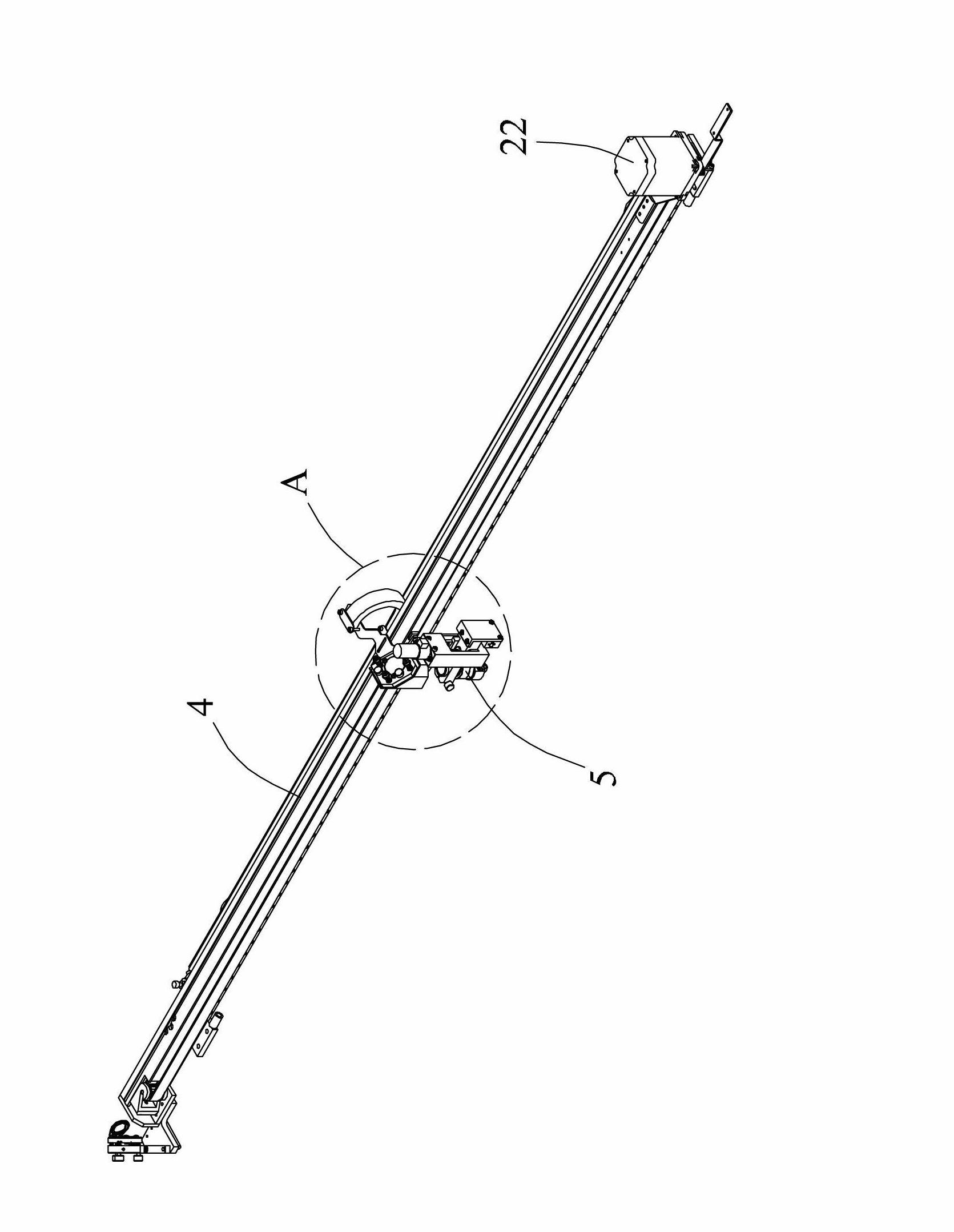
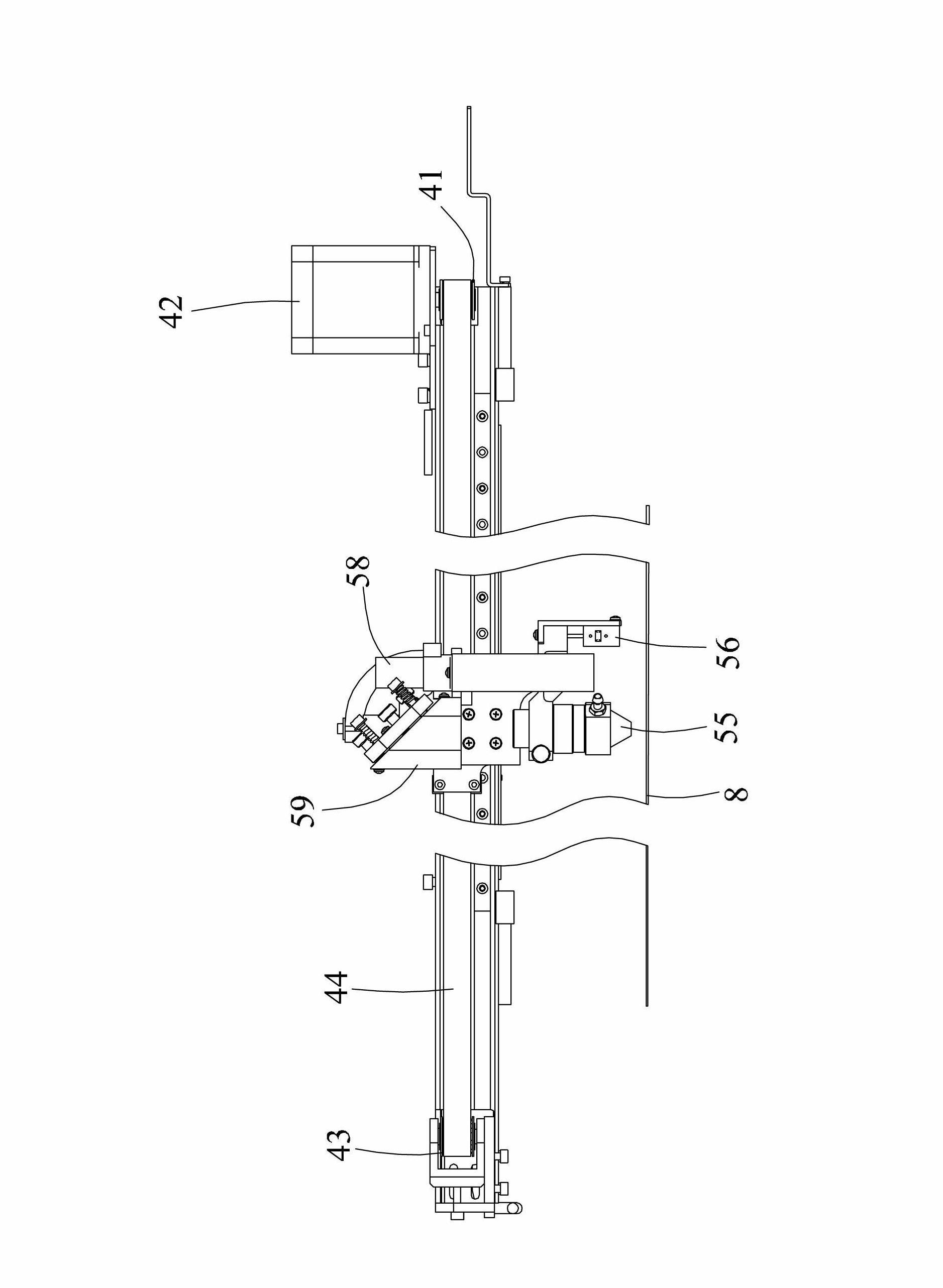
[0028] Such as Figure 1 to Figure 11 Shown is a preferred embodiment of the laser processing apparatus of the present invention.

[0029] The laser processing equipment includes a frame 1, a workbench 2, a pair of guide rail beams 3, a crossbeam 4 and a laser cutting head 5. The left and right sides of the beam 4 are respectively installed on the pair of guide rail beams 3 and can move back and forth along the pair of guide rail beams 3. The laser cutting head 5 is installed on the beam 4 and can move along the beam 4 Moving left and right, the laser cutting head 5 includes a mounting block 51, a linear guide rail 52, a slide block 53, a focusing tube fixing plate 54, a focusing tube 55, a focus sensor 56, a motor fixing plate 57, a linear motor 58 and a mirror holder 59. The laser cutting head 5 is installed on the beam 4 through the mounting block 51, the linear guide rail 52 is vertically fixed on the mounting block 51, and the slider 53 is slidably installed on the linea...


PUM


Abstract

The invention relates to laser machining equipment which comprises a frame, an operating platform, a pair of guide rail beams, a beam and a laser cutting head. The operating platform is arranged on the frame; the pair of the guide rail beams are respectively arranged on left and right sides of the operating platform; two ends of the beam are respectively installed on the pair of the guide rail beams and can move forward and rearward along the pair of the guide rail beams; the laser cutting head is installed on the beam and can move leftward and rightward along the beam; the laser cutting head is provided with a linear motor, so as to drive a focusing tube to move longitudinally along the vertical direction; and a focal length sensor is also provided, so as to realize the automatic switching of automatic focusing, dynamic defocusing carving and sharp focus cutting during machining. The laser machining equipment can realize automatic focusing and defocusing, is suitable for performing rapid machining on light guide plates, and is convenient to operate.

Description

technical field [0001] The invention relates to a laser processing device, in particular to a laser processing device which can be used for processing a light guide plate. Background technique [0002] The use of laser processing equipment to process light guide plates has gradually become popular, but currently the laser processing equipment for processing light guide plates on the market can only be processed by plane processing, and the processing technology has a bitmap (or vector filling map) engraving And dash type two. The main disadvantages of using bitmap (or vector filling map) engraving are long processing time and low production efficiency, while the use of scribing type has poor light guiding effect. Contents of the invention [0003] Therefore, the object of the present invention is to provide a laser processing device capable of realizing automatic focusing and defocusing, which is suitable for fast processing of light guide plates. [0004] In order to ac...

Claims


Application Information

Patent Timeline
IPC IPC(8): B23K26/36B23K26/08B23K26/06B23K26/04B23K26/42B23K26/046B23K26/70
Inventor 王亮郑其锋倪伟平
Owner GUANGDONG HANS YUEMING LASER GRP CO LTD
Learn More