Mechanical pencil

A technology of mechanical pencils and refills, applied in mechanical pencils, printing, writing utensils, etc., can solve a lot of time and cost problems, and achieve the effect of reducing time and cost

Active Publication Date: 2012-08-22
MITSUBISHI PENCIL CO LTD
View PDF9 Cites 2 Cited by
  • Summary
  • Abstract
  • Description
  • Claims
  • Application Information

AI Technical Summary

Problems solved by technology

In particular, with regard to the above-mentioned rotary drive mechanism part that requires a high level of design experience, there is a problem that a lot of time and money are required for a new development and design corresponding to the change in the arrangement position in the shaft cylinder.

Method used


Image

  • Mechanical pencil
  • Mechanical pencil
  • Mechanical pencil

Examples


Embodiment Construction

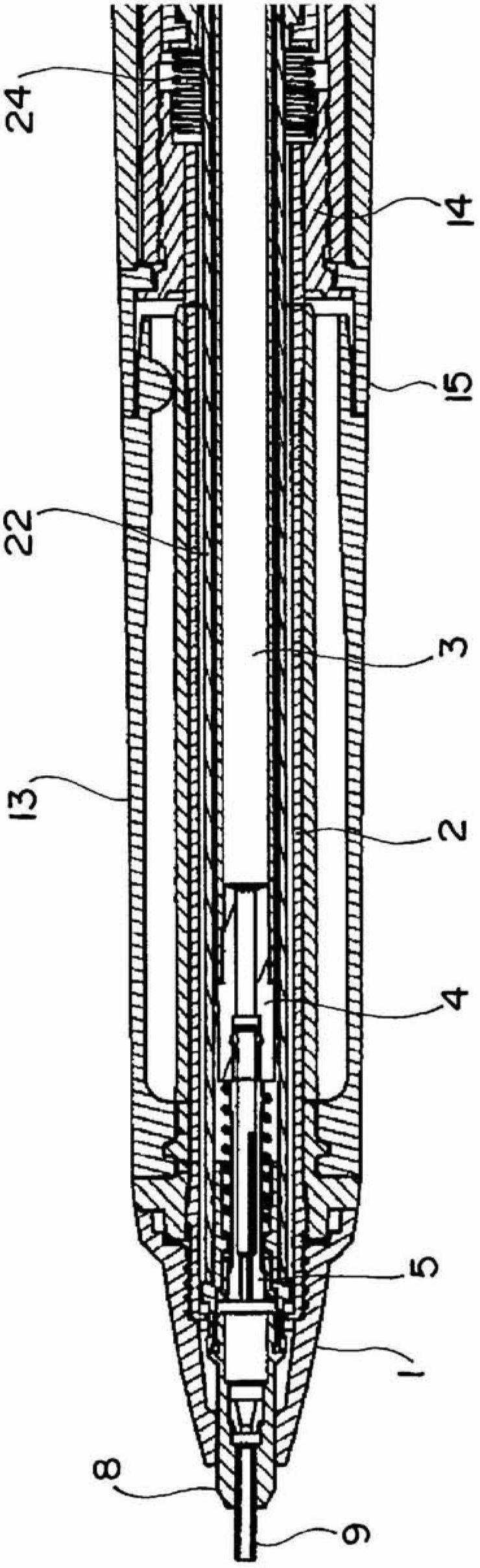
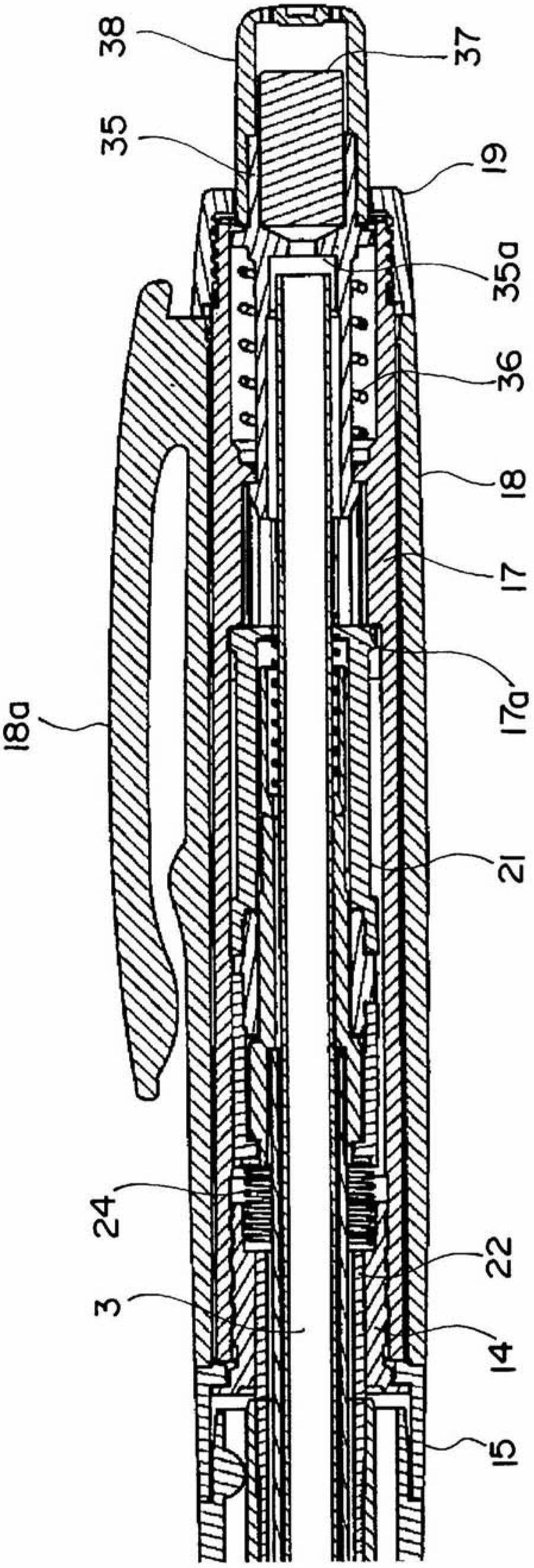
[0046] The mechanical pencil of the present invention will be described based on the illustrated embodiments. figure 1 and figure 2 The overall structure is shown in cross-sectional view, figure 1 Indicates the front half of the mechanical pencil, figure 2 Indicates the second half. In addition, in each figure shown below, the same parts are denoted by the same reference numerals, and in figure 1 and figure 2 In the whole figure shown, the code|symbol is attached|subjected to a representative part.

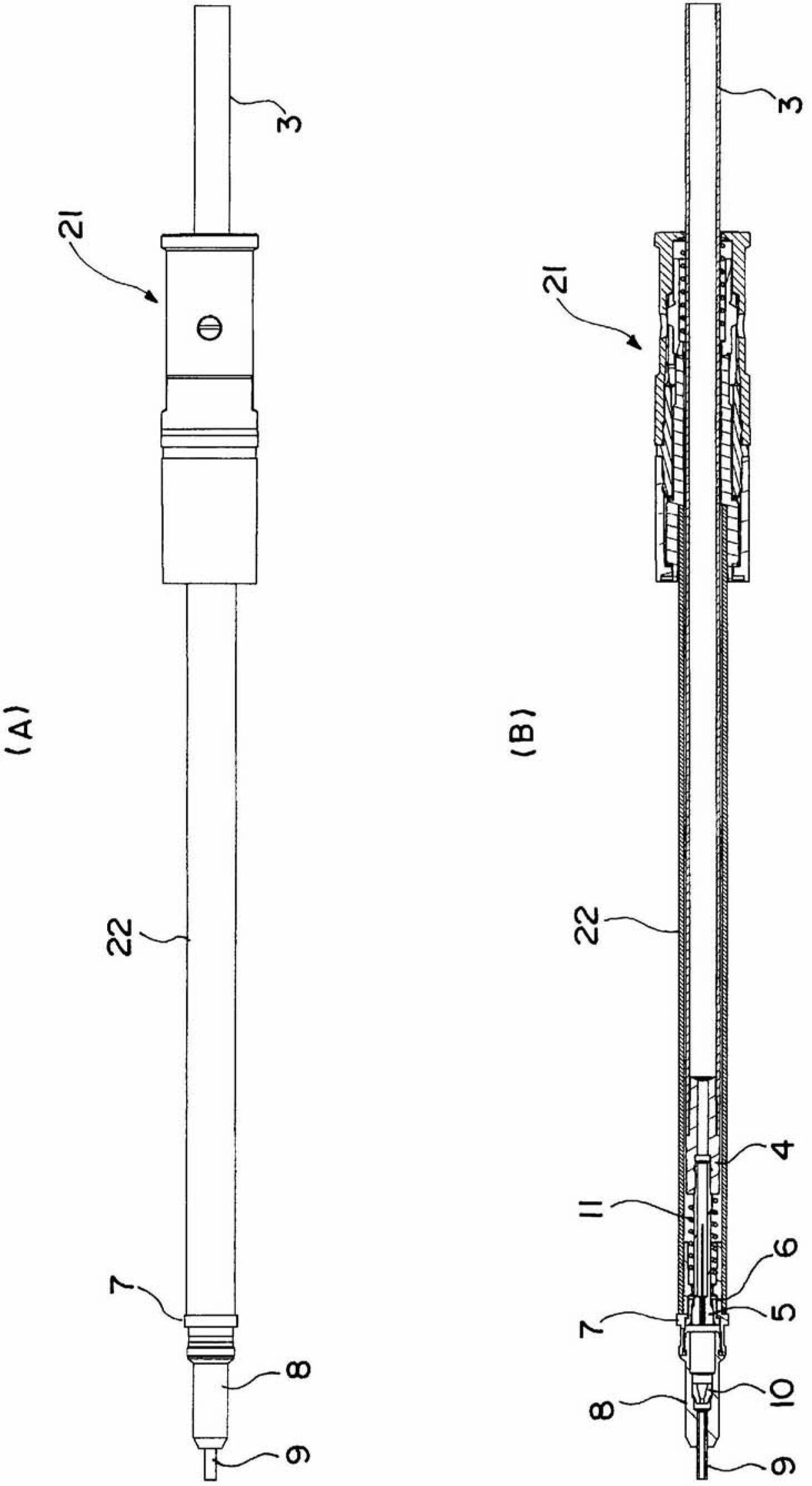
[0047] An outlet end portion (kuchipura) indicated by reference numeral 1 is detachably attached by screwing to the front end portion of a front shaft 2 constituting a shaft cylinder made of a metal material. Further, a cylindrical core box 3 is housed coaxially along the center portions of the front shaft 2 and a rear shaft described later. At the front end of the core box 3 such as image 3 As shown, a short-axis core box connector 4 is attached, and a brass collet 5 i...


PUM


Abstract

A mechanical pencil is configured so as to be able to push a writing lead forward by releasing and gripping said writing lead by means of the frontward and backward movements of a chuck (5), said movement being performed on the basis of the knock operation of a knock member. Moreover, while gripping the writing lead, the chuck is housed in a shaft tube in a manner so as to be able to move frontward and backward, and to be able to rotate about an axis. A rotation driving mechanism (21) which can change the reciprocating movement in the axial direction to a rotational movement is configured as one unit independent from the mechanical pencil main body, and is housed within the aforementioned shaft tube. The rotation driving mechanism (21) and the chuck (5) are connected via a relay pipe (22). By configuring the rotation driving mechanism as one unit independent from the mechanical pencil main body, the rotation driving mechanism becomes versatile in that said mechanism can be used in mechanical pencils with various configurations.

Description

technical field [0001] The present invention relates to a mechanical pencil capable of rotating a lead (replacement lead) by using writing pressure. Background technique [0002] When writing with a mechanical pencil, it is generally not used with the barrel perpendicular to the writing surface (paper surface), but is often used with the barrel slightly inclined relative to the writing surface. . In this way, when writing is performed with the barrel tilted, the pen core will be worn unevenly (one-sided decrease) as the writing progresses, so the stroke line will become thicker than when the writing started. In addition, not only the thickness of the stroke line changes, but also the contact area between the pen core and the writing surface changes, so the density of the stroke line also changes (stroke line becomes lighter) as writing progresses. [0003] In order to avoid the above-mentioned problems, when writing is performed while rotating the barrel, the tip side of t...

Claims


Application Information

Patent Timeline
Patent Type & Authority Applications(China)
IPC IPC(8): B43K21/16
CPCB43K23/008B43K21/006B43K21/02B43K21/16B43K21/22
Inventor 中山协小林武井泽弘壮
Owner MITSUBISHI PENCIL CO LTD
Why Eureka
Try Eureka