Water-cooling type high-frequency transformer and secondary rectifier

A high-frequency transformer and secondary rectification technology, applied in the direction of transformer/inductor cooling, transformer, fixed transformer, etc., can solve the problems of switching power supply operation efficiency and stability, difficult installation, low space utilization, etc., to achieve Transformer secondary winding and rectifier circuit are compact, with little mutual interference and good heat dissipation

Active Publication Date: 2012-08-22
广州爱申特科技股份有限公司
View PDF12 Cites 6 Cited by
  • Summary
  • Abstract
  • Description
  • Claims
  • Application Information

AI Technical Summary

Problems solved by technology

However, high-frequency switching power supplies have strict requirements on heat dissipation and connection resistance. At present, copper bars and wires are generally used as connecting wires and secondary windings of high-frequency transformers in the connection mechanisms of high-current high-frequency switching power supplies. Long, complex structure, high process requirements, difficult installation, easy to cause problems such as large connection resistance, temperature rise, large leakage inductance, and low space utilization, which have a great impact on the operating efficiency and stability of switching power supplies

Method used


Image

  • Water-cooling type high-frequency transformer and secondary rectifier
  • Water-cooling type high-frequency transformer and secondary rectifier
  • Water-cooling type high-frequency transformer and secondary rectifier

Examples


Embodiment Construction

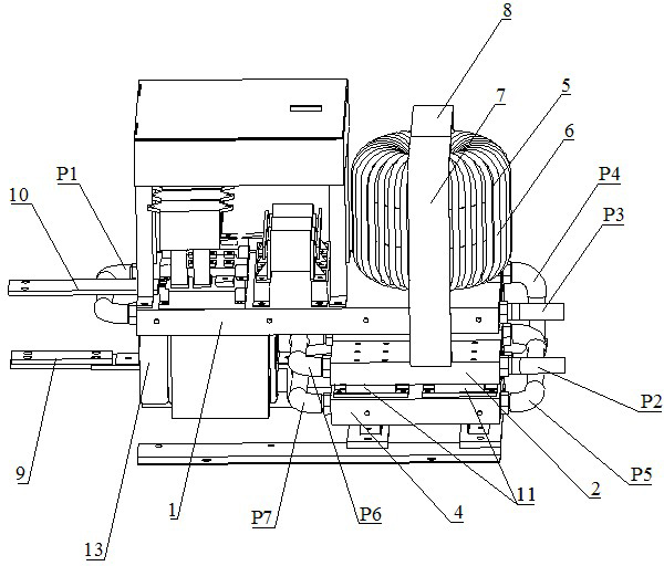
[0015] The present invention will be further described below in conjunction with the accompanying drawings and specific embodiments.

[0016] like Figure 1~3 As shown, the high-frequency transformer and the secondary rectifier include a first water-cooled heat sink 1, a second water-cooled heat sink 2, a third water-cooled heat sink 3, a fourth water-cooled heat sink 4, a ring magnetic core 5, and a transformer primary winding 6. The first copper bar 7, the second copper bar 8, the first group of common cathode rectifier diode modules 11, and the second group of common cathode rectifier diode modules 12; the first water-cooled heat sink 1 serves as the installation base and power supply of the entire power supply structure The negative pole, the fourth water-cooled heat sink 4 is used as the positive pole of the power supply, the primary winding of the transformer is wound 6 on the ring core 5, the ring core 5 is installed on the first water-cooled heat sink 1, and the first ...


PUM


Abstract

The invention discloses a water-cooling type high-frequency transformer and a secondary rectifier. The water-cooling type high-frequency transformer and the secondary rectifier comprise four water-cooling radiating fins, an annular magnetic core, a transformer primary winding, two copper bars and two groups of common-cathode rectification diode modules, wherein the first water-cooling radiating fin serves as a mounting base and a cathode of a power supply of a whole structure of the power supply, the fourth water-cooling radiating fin serves as an anode of the power supply, the annular magnetic core wound with the transformer primary winding is arranged on the first water-cooling radiating fin, cathodes of the two groups of common-cathode rectification diode modules are symmetrically connected with the fourth water-cooling radiating fin, anodes of the two groups of common-cathode rectification diode modules are respectively connected together by the second water-cooling radiating fin and the third water-cooling radiating fin, penetrate through the copper bars of the annular magnetic core respectively and are connected with the first water-cooling radiating fin, so as to form the transformer primary winding and the secondary rectifier. The water-cooling type high-frequency transformer and the secondary rectifier are very compact and concise in structure, uniform in heat distribution and good in radiating effect and has the advantages that a connecting resistance is small, the leakage inductance is small, and the mutual interference is small, thereby being particularly suitable for the field of a water-cooled high-power high-frequency switch power supply.

Description

technical field [0001] The invention relates to a low-voltage, high-current, high-frequency switching power supply transformer and a secondary rectifier for the production of polysilicon, electroplating, electrolysis, electric vehicle charging and other industries, in particular to a water-cooled high-frequency transformer and a secondary rectifier. Background technique [0002] Polysilicon production, electroplating, electrolysis, electric vehicle charging and other industries require high-power power supplies. Due to the small size, light weight, good adaptability, and good dynamic performance of high-frequency switching power supplies, it is conducive to the realization of automation and intelligent control. Thyristors are gradually replaced rectified power supply. However, high-frequency switching power supplies have strict requirements on heat dissipation and connection resistance. At present, copper bars and wires are generally used as connecting wires and secondary wi...

Claims


Application Information

Patent Timeline
Patent Type & Authority Applications(China)
IPC IPC(8): H01F30/06H01F27/16H01F27/40H02M7/219
Inventor 杜贵平何正东
Owner 广州爱申特科技股份有限公司
Why Eureka
Try Eureka