
Automatic diagnostic device and diagnostic method of long-distance magnetic array position sensing system

A sensing system and automatic diagnosis technology, applied in the direction of measuring devices, using electrical devices, using electromagnetic means, etc., can solve problems such as increasing the complexity of hardware circuit and software design, reducing system stability, increasing design costs, etc., to achieve simplification System hardware circuit and software design, the effect of improving system stability and reliability

Inactive Publication Date: 2012-08-15
WUHAN UNIV
View PDF5 Cites 2 Cited by
  • Summary
  • Abstract
  • Description
  • Claims
  • Application Information

AI Technical Summary

Problems solved by technology

[0004] The present invention mainly solves the technical problems existing in the prior art, which increase the complexity of hardware circuit and software design, increase the design cost, be susceptible to interference and reduce the stability of the system; it provides a simplified system hardware circuit and software An automatic diagnostic device and diagnostic method for a long-distance magnetic array position sensing system that reduces cost, reduces interference, and improves system stability

Method used


Image

  • Automatic diagnostic device and diagnostic method of long-distance magnetic array position sensing system
  • Automatic diagnostic device and diagnostic method of long-distance magnetic array position sensing system
  • Automatic diagnostic device and diagnostic method of long-distance magnetic array position sensing system

Examples


Embodiment

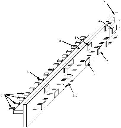
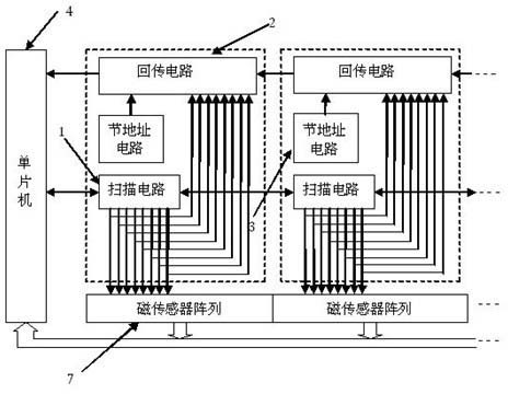
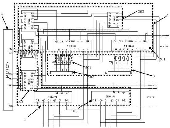
[0026] First introduce the structure of the device used in the present invention, including several section circuit boards connected end to end by the fixing device, that is, the first section circuit board, the second section circuit board ... the N section circuit board; the first section circuit board or the N section circuit board There is also a main control circuit board fixed on the circuit board by a fixing device; the main control circuit board is provided with a main control unit; the first section circuit board, the second section circuit board...the N section circuit board are respectively provided with the first section connected in sequence The 1st diagnostic circuit, the 2nd diagnostic circuit ... the Nth diagnostic circuit; the 1st diagnostic circuit, the 2nd diagnostic circuit ... the Nth diagnostic circuit are also connected to the main control system at the same time, and the fixing device includes a pin connection board 11, the pin One end of the connecting ...


PUM


Abstract

The invention relates to an automatic diagnostic device and diagnostic method of a long-distance magnetic array position sensing system. The automatic diagnostic device comprises a plurality of sections of circuit boards, namely a first section of circuit board, a second section of circuit board,..., and an Nth section of circuit board, which are connected head to tail by a fixing device, wherein the first section of circuit board or the Nth section of circuit board is fixed with a main control circuit board through the fixing device; the main control circuit board is provided with a main control unit; the first section of circuit board, the second section of circuit,..., and the Nth section of circuit board are respectively provided with a first diagnosis circuit, a second diagnosis circuit,..., and an Nth diagnosis circuit; and the first diagnosis circuit, the second diagnosis circuit,..., and the Nth diagnosis circuit are simultaneously connected with a main control system. The device and the method provided by the invention have the following advantages: the design cost is reduced, the interference is reduced, the system stability is improved, and a shift register cascade is used for the long-distance expansion to realize no restrictions on the measuring distance theoretically; and in addition, the system can be ensured to work in the case of individual damaged sensing element and obviously improve the power-on reliability of the long-distance scanning of the system.

Description

technical field [0001] The invention relates to an automatic diagnosis device and a diagnosis method for a sensing system, in particular to an automatic diagnosis device and a diagnosis method for a long-distance magnetic array position sensing system. Background technique [0002] A moving ruler with a permanent magnet array is installed on one object, and a static ruler with a magnetic sensor array and a circuit is installed on another object. The magnetic sensitive element array on the static ruler receives the periodic magnetic field of the permanent magnet array on the moving ruler and sends a signal. The technique of processing to measure the relative displacement of two objects is widely used. This type of device has the advantages of no wear, resistance to harsh environments, fast response speed, etc., and high measurement accuracy, and has been made into a dedicated integrated circuit such as HLA32, which has a 32-way Hall element array and uses a single-chip microc...

Claims


Application Information

Patent Timeline
IPC IPC(8): G01B7/00
Inventor 曹大平王捷蒋昌忠
Owner WUHAN UNIV
Learn More