
Resin pressing curved surface numerical control machining clamp for performing precision forging on blade tenon root

A fixture and resin technology, used in manufacturing tools, metal processing equipment, metal processing machinery parts, etc., can solve the problems of large positioning error, large clamping deformation, insufficient stability, etc., achieve high positioning accuracy, and solve the problem of clamping , the effect of easy installation

Inactive Publication Date: 2012-08-15
NORTHWESTERN POLYTECHNICAL UNIV
View PDF6 Cites 17 Cited by
  • Summary
  • Abstract
  • Description
  • Claims
  • Application Information

AI Technical Summary

Problems solved by technology

[0006] In order to avoid the shortcomings of the existing technology and overcome the problems of large positioning error, insufficient stability and large clamping deformation caused by the positioning of the tenon root of the precision forged blade through the curved surface of the blade body during processing, the present invention proposes a resin compaction Curved Surface NC Machining Precision Forging Blade Tenon Root Fixture
The purpose is to enable the blade to withstand the impact and vibration caused by the cutting force of the tool during processing, so that the processing of the blade is stable and not easily deformed, and the positioning accuracy is improved; the fixture can not only improve the processing efficiency of the aero-engine blade, but also improve the processing accuracy , to solve the clamping problem when processing precision forging blade tenon root

Method used


Image

  • Resin pressing curved surface numerical control machining clamp for performing precision forging on blade tenon root
  • Resin pressing curved surface numerical control machining clamp for performing precision forging on blade tenon root
  • Resin pressing curved surface numerical control machining clamp for performing precision forging on blade tenon root

Examples


Embodiment Construction

[0024] This embodiment is a resin-compressed curved surface numerically controlled precision forging blade tenon root fixture.

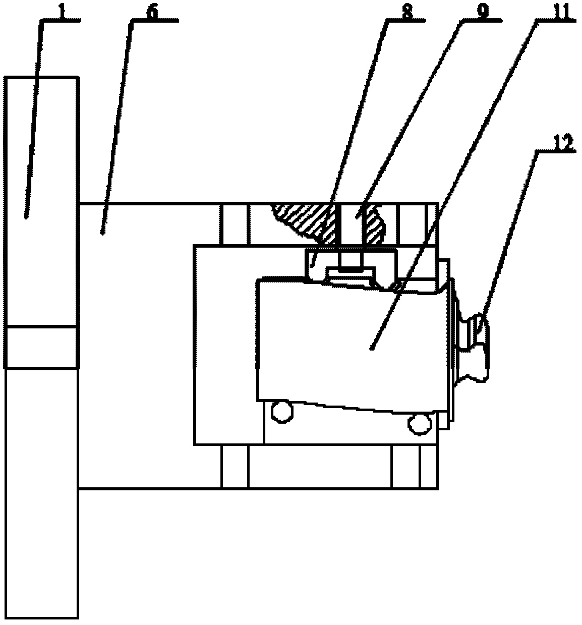
[0025] refer to figure 1 , figure 2 , image 3 , Figure 4 , the resin-pressed curved surface numerically controlled precision forging blade tenon root fixture of the present invention includes a rotary table 1, a fixture box cover 2, a box cover top plate 3, a positioning pin 3 4, an eccentric pin shaft 5, a fixture box body 6, and an upper bolt 7 , adjusting block 8, positioning screw 9, fastening pin one 10, blade 11, blade tenon root 12, blade body positioning pin one 13, lower bolt 14, blade body positioning pin two 15, metal belt one 16, metal belt two 17 , metal strip three 18, metal strip four 19, box top plate 20, positioning pin two 21, positioning pin one 22, fastening pin two 23;

[0026] The rotary table 1 is fixed and installed on the machine tool table by bolts; the fixture box 6 fixed on the rotary table 1 is connected with the f...


PUM


Abstract

The invention discloses a resin pressing curved surface numerical control machining clamp for performing precision forging on a blade tenon root. A clamp box cover is connected with a clamp box body through an eccentric pin shaft; parts of the clamp box body and the clamp box cover, which are contacted with a blade back, a blade basin and the tenon root, are made of resin materials, so that a blade can bear impact and vibration which are caused by a cutting force of a cutter during machining, and the blade can be machined stably and is deformed difficultly; and the positioning precision is improved. According to the clamp, the efficiency of machining an aircraft engine blade is improved, and the machining precision of the clamp can be improved, so that the problem about clamping during blade tenon root precision forging is solved. The clamp has a simple structure and is convenient to mount and high in positioning precision; and the clamp can be assembled and disassembled frequently without influencing the positioning precision. The clamp is used for machining the tenon root of the aircraft engine blade and tenon roots of similar thin wall blades, such as a working blade of a gas turbine, a guide blade and the like.

Description

technical field [0001] The invention relates to a fixture for positioning and processing precision-forged blade tenon roots on curved surfaces, in particular to a resin-compressed curved surface numerically controlled machining precision-forged blade tenon root fixtures. The invention belongs to the technical field of aeroengine blade processing. Background technique [0002] Aeroengine blades are typical complex curved surfaces with high degrees of freedom. Thin-walled blades have the characteristics of bending, twisting, and sweeping. They require high surface accuracy and good aerodynamic performance; the high-precision characteristics of blades make their processing efficiency low. Moreover, quite high requirements are also put forward for the tooling and fixtures before blade processing. In order to improve the processing efficiency, some relatively small blades can be processed by the high-efficiency method of precision forging. The existing precision forging technol...

Claims


Application Information

Patent Timeline
Patent Type & Authority Applications(China)
IPC IPC(8): B23Q3/06
Inventor 刘维伟李晓燕万旭生单晨伟黄新春史耀耀
Owner NORTHWESTERN POLYTECHNICAL UNIV
Learn More