
Online detection and correction system for laser-guided deep-hole drilling

A laser-guided and deep-hole drilling technology, which is applied in the direction of drilling/drilling equipment, positioning measurement in boring machines/drilling machines, manufacturing tools, etc., can solve problems such as difficult observation of processing parts and tool conditions, and achieve the promotion of deviation correction problems, The effect of improving parallelism

Active Publication Date: 2012-08-15
ZHONGBEI UNIV
View PDF3 Cites 14 Cited by
  • Summary
  • Abstract
  • Description
  • Claims
  • Application Information

AI Technical Summary

Problems solved by technology

[0004] Purpose of the present invention: In order to solve the problem that it is difficult to observe the processing position and the status of the tool in the existing deep hole machining process, provide a real-time detection method using laser for the workpiece rotation, drill feed, and internal chip removal deep hole drilling process. The position and attitude (that is, angle) of the deep hole drill with internal chip removal, and the detection and correction system that automatically adjusts the attitude of the drill as needed to restore it to the initial value

Method used


Image

  • Online detection and correction system for laser-guided deep-hole drilling
  • Online detection and correction system for laser-guided deep-hole drilling
  • Online detection and correction system for laser-guided deep-hole drilling

Examples


Embodiment 1

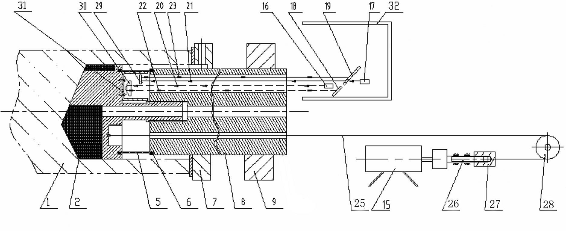
[0043] Embodiment 1: as figure 1 As shown, the workpiece 1 of the present invention rotates and the drill bit 2 feeds. There is no bottom hole in the workpiece, and a deep hole with a horizontal axis needs to be drilled.

[0044] The present invention comprises workpiece 1, drill bit 2, drill pipe 8, oil feeder 7, feed box 9, No. 1 light source 16, No. 2 light source 17, drill bit position sensor 18, drill bit attitude sensor 19, reflecting mirror 29, cube pyramid Prism 30, stay cord 25, the motor 15 that corrects drill bit usefulness, computing controller, computer.

[0045] The drill bit 2 is fixed on the drill rod 8 through its threaded section 42, and the drill rod 8 is fixed on the feed box 9 for only feeding motion. The oil feeder 7 provides high-pressure oil for deep hole processing. The oil flows in from the hole of the oil feeder 7, passes through the gap between the drill rod 8 and the workpiece 1 and the gap between the blades 38 of the drill bit 2, and is dischar...

Embodiment 2

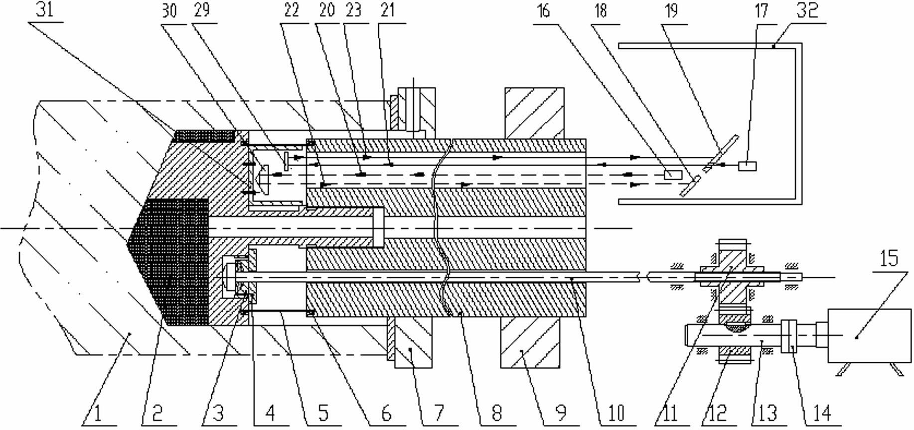
[0058] Embodiment 2: as figure 2 As shown, the afterburning mechanism adopts the form of a tie rod.

[0059] Pull rod type force adding mechanism, the pull rod head is positioned at the connecting hole 45 of the drill bit back, and the pull rod head acts on the spherical washer 3, and the spherical washer acts on the cover 4, and the cover is fixed in the connecting hole 45 on the drill bit back. The motor 15 drives the output shaft 13 through the coupling 14, and drives two gears (or pulleys) to rotate. The axial movement of the gear 11 is limited by the parts fixed on the feed box. The inner hole of the gear 11 is threaded, and the pull rod The threads at the rear end cooperate to drive the pull rod 10 . Other structures are with embodiment 1.


PUM


Abstract

The invention belongs to the technical field of inner-chip removal deep-hole processing, and particularly relates to an online detection and correction system for laser-guided deep-hole drilling, which solves the problem that processed parts and tool conditions are difficultly observed in the existing deep-hole processing process. The online detection and correction system for laser-guided deep-hole drilling comprises a detection part and a correction part, wherein the detection part comprises a light source, a drill stem is provided with a light-passing hole and a light beam receiving area, two incident light beams emitted from the light source are formed into two channels of return light beams, and then the return light beams reach a bit position sensor and a bit attitude sensor; and the correction part comprises a stressing mechanism and a plurality of stressing holes, wherein the plurality of stressing holes are arranged on the drill stem, and the stressing mechanism passes through the stressing holes and then is connected with the back surface of a bit. The system disclosed by the invention has the advantages that the operating conditions of workpiece rotation and bit-fed deep-hole processing can be mastered timely, and the attitude deviation of the bit can be timely corrected, thereby promoting the solution to correction problems in deep-hole processing, and improving the straightness of deep holes and the parallelism, verticality and coaxiality of deep holes relative to a design basis.

Description

technical field [0001] The invention belongs to the technical field of internal chip removal deep hole processing, and in particular relates to an online detection and deviation correction system for laser-guided deep hole drilling. Background technique [0002] Deep hole processing mainly includes drilling and boring. Boring expands the original bottom hole. Drilling usually refers to processing holes on a solid body. Before drilling, there is no bottom hole. According to the chip removal method, the deep hole drills are mainly divided into: inner chip removal deep hole drill and outer chip removal deep hole drill. The main methods of deep hole machining are: first, the tool rotates and the workpiece is fed; second, the workpiece rotates and the tool is fed. [0003] Deep hole processing is a difficult point in mechanical processing. It is difficult to observe the processing part and the condition of the tool during the processing. Therefore, real-time detection of deep ho...

Claims


Application Information

Patent Timeline
Patent Type & Authority Applications(China)
IPC IPC(8): B23B49/00
Inventor 沈兴全于大国庞俊忠黄晓斌李艳兰
Owner ZHONGBEI UNIV
Learn More