Production equipment used for thin slab continuous casting

A thin slab continuous casting and production equipment technology, applied in the thin slab processing field, can solve problems such as the inability to satisfactorily solve thin slab cracks, affecting the market share of enterprise products, continuous casting production and product quality hazards, etc. degree and market share, crack reduction, and the effect of improving product quality

Inactive Publication Date: 2012-08-15
MAGANG (GROUP) HOLDING CO LTD +1
View PDF8 Cites 0 Cited by
  • Summary
  • Abstract
  • Description
  • Claims
  • Application Information

AI Technical Summary

Problems solved by technology

[0003] The above are the main measures taken to reduce longitudinal cracks in the current thin slab continuous casting process. However, since the longitudinal cracks are caused by the combined effects of various factors, the production quality of thin slabs is affected by the composition and temperature of molten steel, pouring technology, and cast slabs. The comprehensive influence of the cooling of the guide section and the condition of the equipment, therefore, the solutions in the prior art cannot satisfactorily solve the problem of cracks in the thin slab
However, thin slabs are prone to longitudinal cracks, which require special cleaning if they are mild, or blockage of coils or even longitudinal cracks and breakouts if they are severe, which will bring great harm to continuous casting production and product quality, and affect the market share of the company's products.

Method used


Image

  • Production equipment used for thin slab continuous casting
  • Production equipment used for thin slab continuous casting
  • Production equipment used for thin slab continuous casting

Examples


Embodiment Construction

[0018] Below with reference to the accompanying drawings, through the description of the embodiments, the specific embodiments of the present invention, such as the shape, structure, mutual position and connection relationship between the various parts, the role and working principle of the various parts, etc., will be further described. Detailed instructions:

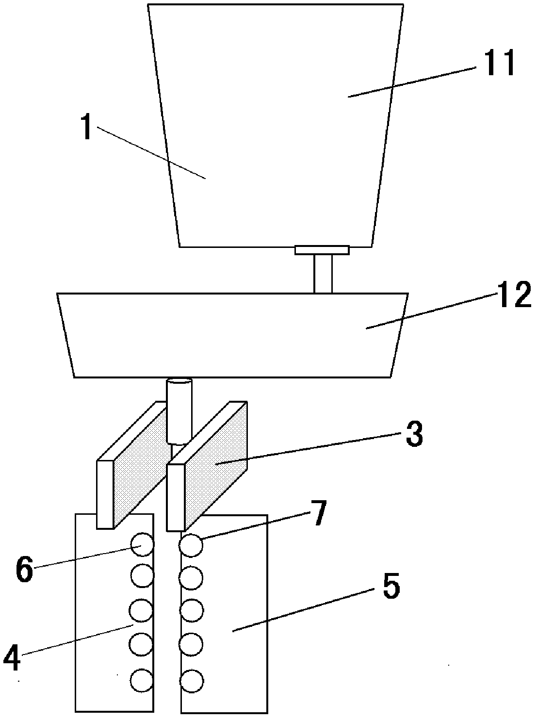
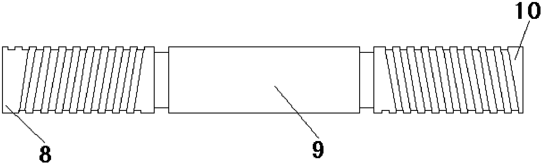
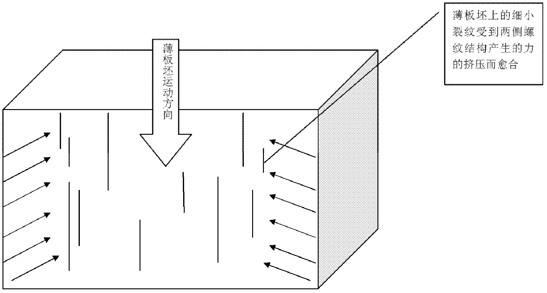
[0019] as attached figure 1 , attached figure 2 , attached image 3 As shown, the present invention is a thin slab continuous casting production equipment, including a ladle 1, a crystallizer 2, a continuous casting guide segment 3, the crystallizer 2 is arranged under the ladle 1, and the continuous casting guide segment 3 is arranged in the crystallizer Below 2, after the thin slab exits the crystallizer 2, it enters the continuous casting guide segment 3, on which the strand guide roller group I4 and the strand guide roller group II5 are installed, the strand guide roller group I 4 and strand guide roller group ...


PUM


Abstract

The invention provides production equipment used for thin slab continuous casting, applied to the technical field of thin slabs. The production equipment comprises a steel ladle (1), a crystallizer (2) and a continuous casting guiding segment (3), wherein a thin slab enters into the continuous casting guiding segment (3) after being taken out from the crystallizer (2), the continuous casting guiding segment (3) is provided with a casting blank guide roller group I (4) and a casting blank guide roller group II (5), the casting blank guide roller group I (4) and the casting blank guide roller group II (5) respectively comprise multiple casting blank guide rollers I (6) and multiple casting blank guide rollers II (7) which are arranged in parallel, and the casting blank guide rollers I (6) and the casting blank guide rollers II (7) are of structures with thread lines. The production equipment used for thin slab continuous casting disclosed by the invention can realize the effect of repairing cracks on a thin slab, thus the number of the cracks is obviously reduced on the thin slab produced by adopting the production equipment disclosed by the invention, and scratches are almost entirely eliminated.

Description

technical field [0001] The invention belongs to the technical field of thin slab processing, and more specifically relates to a production equipment for thin slab continuous casting. Background technique [0002] The origin of the longitudinal cracks in the thin slab is the inhomogeneity of the thickness of the primary solidified shell in the meniscus region of the mold, mainly due to the uneven heat transfer between the molten steel-slab shell-mold slag-copper plate in the mold, which leads to uneven solidification. Cracks will continue to expand in the secondary cooling zone after the crystallizer. At the same time, longitudinal cracks mainly occur at 1 / 2 to 1 / 4 of the wide surface of the copper plate, which is also related to the stress of the mold surface on the billet shell. At present, the following measures are mainly taken to control thin slab cracks: 1. Realize by controlling the composition and temperature of molten steel; 2. Realize by controlling the pouring ope...

Claims


Application Information

Patent Timeline
IPC IPC(8): B22D11/04B22D11/12
Inventor 周立宏乌力平张艳
Owner MAGANG (GROUP) HOLDING CO LTD
Why Eureka
Try Eureka