Potential energy recovery system for vehicles

A potential energy recovery, vehicle technology, applied in the direction of vehicle components, pneumatic power units, the arrangement of multiple different prime movers of general power units, etc. To achieve the effect of reducing exhaust gas pollution, reducing fuel consumption, and reducing emissions

Inactive Publication Date: 2012-08-01
田丽欣
View PDF5 Cites 7 Cited by
  • Summary
  • Abstract
  • Description
  • Claims
  • Application Information

AI Technical Summary

Problems solved by technology

However, the potential energy of heavy-duty vehicles such as trucks and buses with the highest potential energy recovery in the transportation industry cannot be recovered, and a large amount of energy cannot be reused.
And the existing large vehicles are only driven by fuel or gas internal combustion engines. When the vehicle is running at low speed or the engine is idling, the low combustion efficiency of the internal combustion engine causes unnecessary consumption of fuel or gas.

Method used


Image

  • Potential energy recovery system for vehicles
  • Potential energy recovery system for vehicles
  • Potential energy recovery system for vehicles

Examples


Embodiment Construction

[0017] Attached below figure 1 , attached figure 2 , attached image 3 , attached Figure 4 , attached Figure 5 The present invention will be further described.

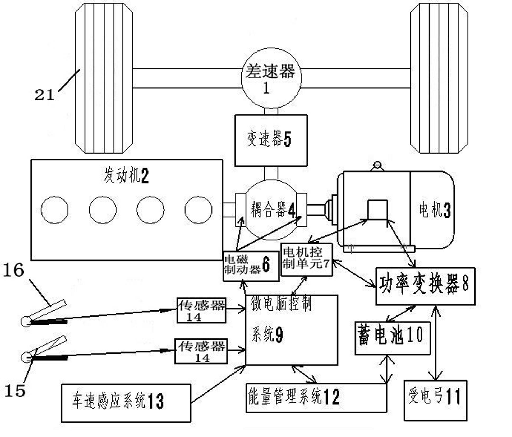
[0018] The present invention provides a vehicle potential energy recovery system, which includes an engine 2, a transmission 5, an accelerator pedal 16, and a brake pedal 15. The transmission 5 is connected to the driving wheel 21 through a differential 1, and the engine 2 is connected to the motor through a coupler 4. 3 is connected with transmission 5. The engine shaft output shaft 4.1 and the motor output shaft 4.10 on both sides of the coupler 4 are each equipped with an electromagnetic brake 6, the microcomputer control system 9 controls the electromagnetic brake 6 through the signal line, and the motor 3 is connected with the power converter 8 and the motor control unit 7 respectively , and the power converter 8 is connected to the motor control unit 7, the battery 10 is connected to the power converter ...


PUM


Abstract

The invention relates to a vehicle device, in particular to a potential energy recovery system for vehicles. The potential energy recovery system comprises the structure that an engine is connected with a transmission through a coupler and a motor; electromagnetic brakes are mounted on an engine output shaft and a motor output shaft, which are arranged on two sides of the coupler; a microcomputer control system controls the electromagnetic brakes through a signal wire; the motor is respectively connected with a power inverter and a motor control unit; the power inverter is connected with the motor control unit; a storage battery is connected with the power inverter; an energy management system is connected with the storage battery; the electromagnetic brakes, the motor control unit, the energy management system and the microcomputer control system are connected; and an accelerator pedal and a brake pedal are respectively connected with the microcomputer control system through sensors. Through the potential energy recovery system for vehicles, the conversion from the kinetic energy of the engine to the electric energy when the engine is in the idle station, the recovery of the braking energy of the vehicles as well as the conversion from the braking energy to the electric energy to be stored in the storage battery are realized, the motor and the engine are connected in parallel through the coupler, and the dual drive can be achieved.

Description

technical field [0001] The invention relates to a vehicle device, in particular to a potential energy recovery system for vehicles. Background technique [0002] It is well known that the energy to be overcome by vehicle braking mainly comes from two aspects: the vehicle's dynamic potential energy and gravitational potential energy. In order to save energy, electric vehicles can use the reversible principle of the motor to recycle the braking energy to achieve the purpose of energy saving. However, the potential energy of heavy-duty vehicles, such as trucks and buses, which have the greatest recyclable potential energy in the transportation industry, cannot be recovered, and a large amount of energy cannot be reused. And existing large-scale vehicle is all only driven by the internal combustion engine of fuel oil or gas, because the combustion efficiency of internal combustion engine at this moment causes unnecessary consumption of fuel oil or gas when vehicle is running at ...

Claims


Application Information

Patent Timeline
Patent Type & Authority Applications(China)
IPC IPC(8): B60K6/22
Inventor 田丽欣
Owner 田丽欣
Why Eureka
Try Eureka