


Quick Research
Generate reliable direction feasibility study reports for your R&D in just a few steps.

Technical Q&A
Discover and master advanced knowledge NOW. Basics, ideas, possibilities, all at once.

Find Solutions
As an expert in R&D theories, this can generate solutions to your technical problems instantly.

Evaluate Feasibility
Analyze your overall solution with one click, know your potential R&D risks in advance.

Monitor Landscape
Get weekly tech updates, stay abreast of the latest tech innovations and key insights.
Stave, blast furnace, and blast furnace operation method
A cooling stave and vertical technology, applied in vertical furnaces, blast furnaces, cooling devices, etc., can solve the problems of wear and surface damage of vertical cooling staves, and achieve the effect of achieving stabilization and preventing the deterioration of the inner contour of the furnace.
- Summary
- Abstract
- Description
- Claims
- Application Information
AI Technical Summary
Problems solved by technology
Method used
Image

Examples
no. 1 Embodiment approach 〕
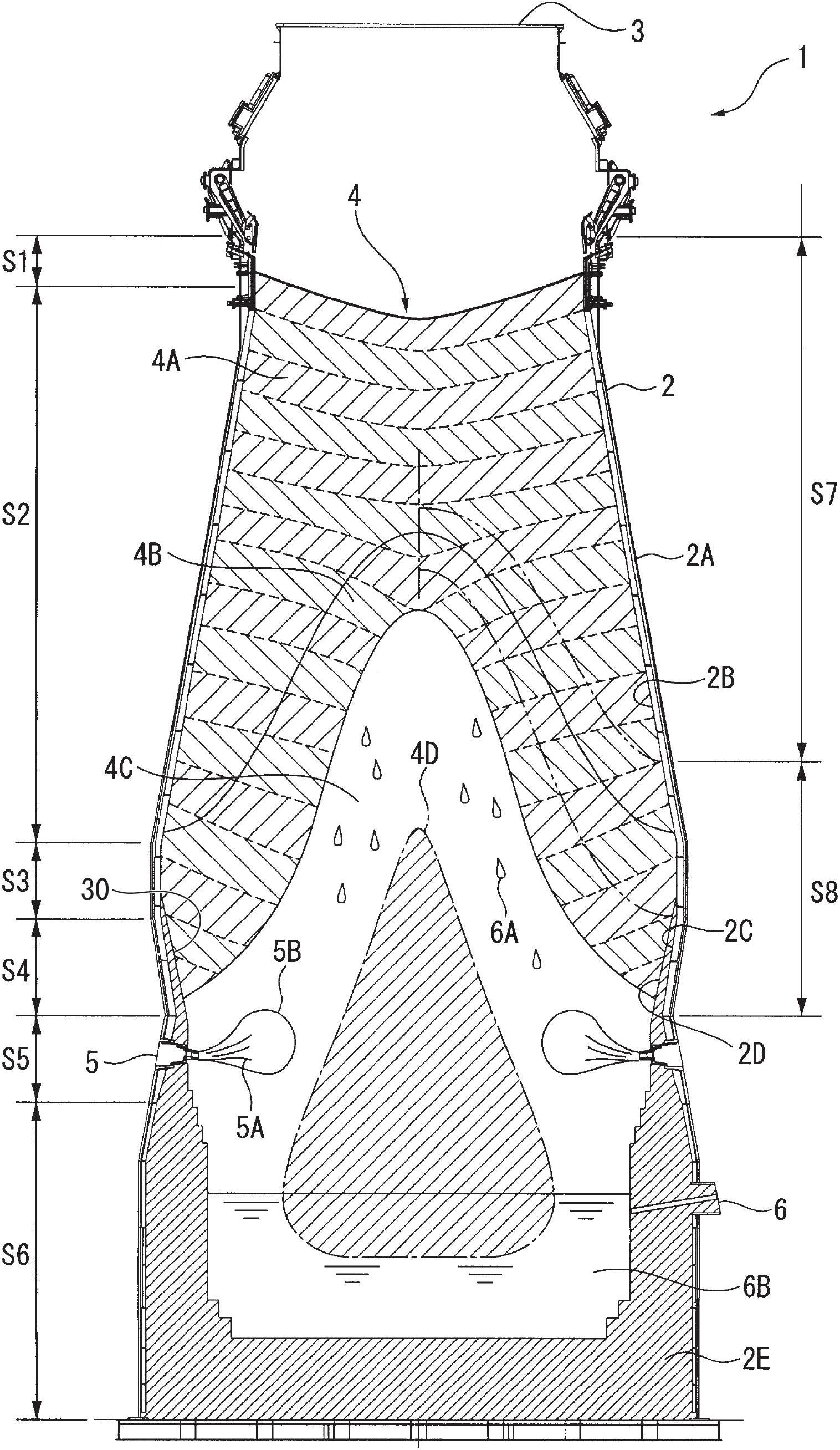
[0068] exist figure 1 Among them, a blast furnace 1 has a cylindrical furnace body 2 constructed on a foundation base.
[0069] The furnace body 2 is cylindrical, and the gas collection mantel 3 at the upper part is sequentially divided into a furnace mouth part S1, a furnace body part S2, a furnace belly part S3, a furnace waist part S4, a tuyere part S5 and a furnace bottom part S6. Usually, the inner diameter of the shaft portion S2 expands downward, the inner diameter of the belly portion S3 becomes the largest diameter, and the inner diameter of the furnace waist portion S4 decreases downward.
[0070] In the furnace body 2 , usually a charging device is arranged on the gas collecting mantel 3 , and the blast furnace 1 is charged with a granular charge 4 by this charging device. As the charge 4 , an ore-based charge with a particle size of about 8 to 25 mm and a coke-based charge with a particle size of about 20 to 55 mm are charged alternately. As a result, massive ban...
no. 2 Embodiment approach 〕
[0157] exist Figure 12 , Figure 13 and Figure 14 , shows the second embodiment of the present invention.
[0158] The stave 20 for the furnace belly and the furnace belly of the present embodiment serves as a stave for the region S8 from the lower part of the furnace shaft S2 in the blast furnace 1 of the above-mentioned first embodiment to the furnace belly S3 and the furnace waist S4. 2C use. The structure of the blast furnace 1 is the same as that of the above-mentioned first embodiment, and the basic structure of the stave 20 installed on the furnace waist S4 and the belly S3 of this embodiment is the same as that of the furnace waist S4 and the belly S3 of the above-mentioned first embodiment. The stave 10 is the same. Therefore, description is abbreviate|omitted about the part common to the stave 10 of said 1st Embodiment, and a different part is demonstrated below.
[0159] exist Figure 12 , Figure 13 and Figure 14Among them, the stave 20 provided on the f...
PUM
| Property | Measurement | Unit |
|---|---|---|
| particle size | aaaaa | aaaaa |
| particle size | aaaaa | aaaaa |
Abstract
Description
Claims
Application Information
 - R&D Engineer
- R&D Manager
- IP Professional
- Industry Leading Data Capabilities
- Powerful AI technology
- Patent DNA Extraction
Browse by: Latest US Patents, China's latest patents, Technical Efficacy Thesaurus, Application Domain, Technology Topic, Popular Technical Reports.
© 2024 PatSnap. All rights reserved.Legal|Privacy policy|Modern Slavery Act Transparency Statement|Sitemap|About US| Contact US: help@patsnap.com