
Ballast for low-frequency electrodeless lamp

A low-frequency electrodeless lamp and ballast technology, applied in the field of electronic ballasts, can solve the problems of insufficient driving voltage of a ballast MOS tube drive circuit, unable to obtain a 13.5V power supply voltage, etc., and achieves simple structure, reasonable design and cost. low cost effect

Inactive Publication Date: 2012-07-25
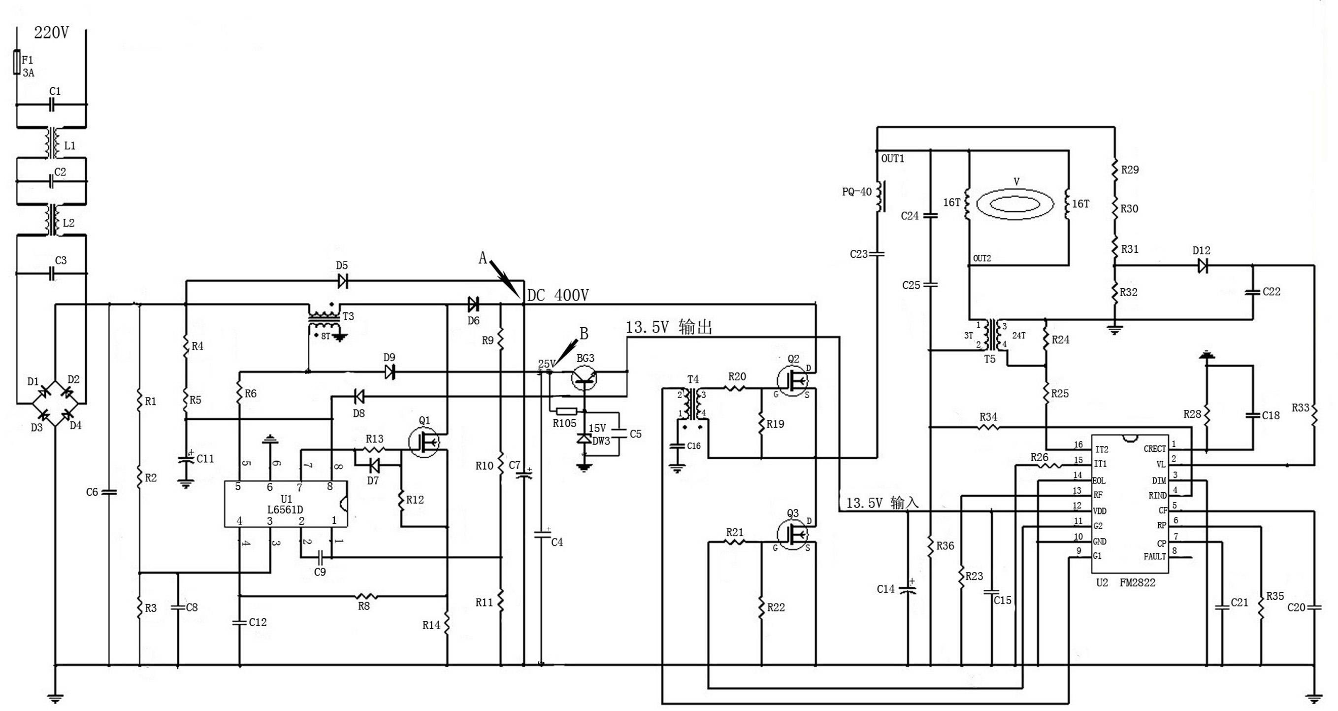
洪路 +1
View PDF3 Cites 1 Cited by
  • Summary
  • Abstract
  • Description
  • Claims
  • Application Information

AI Technical Summary

Problems solved by technology

[0009] In order to solve the problem that the driving voltage of the MOS tube drive circuit in the ballast is insufficient and a stable 13.5V power supply voltage cannot be obtained when the low-frequency electrodeless lamp starts for the first time, the present invention provides a new type of low-frequency electrodeless lamp ballast

Method used


Image

  • Ballast for low-frequency electrodeless lamp
  • Ballast for low-frequency electrodeless lamp
  • Ballast for low-frequency electrodeless lamp

Examples


Embodiment Construction

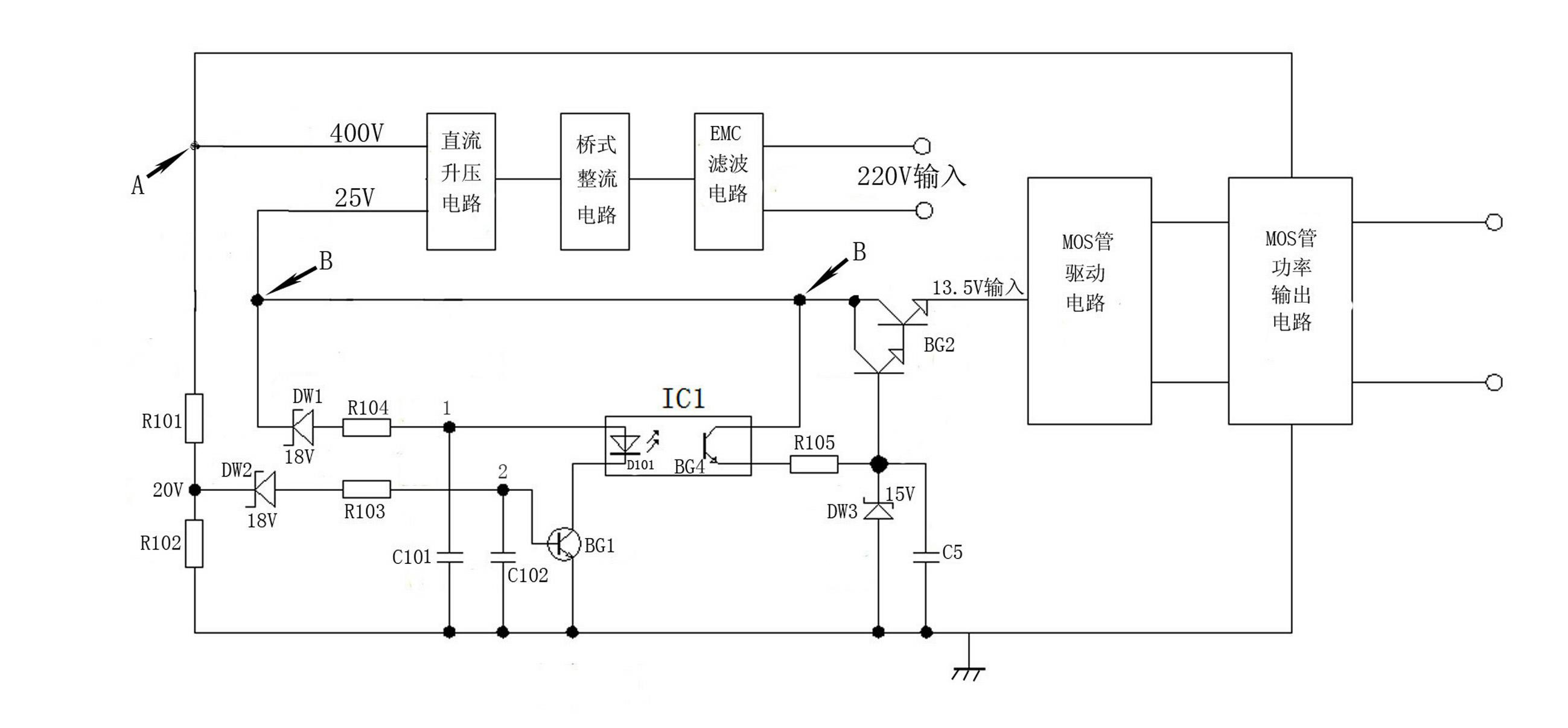
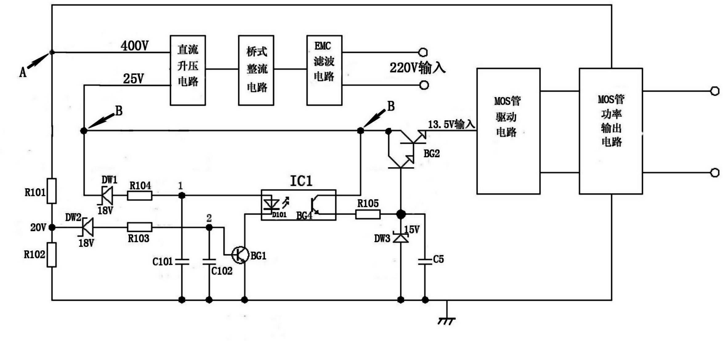
[0025] Combine below figure 1 and figure 2 The present invention will be described in detail.

[0026] A low-frequency electrodeless lamp ballast, including EMC filter circuit, bridge rectifier circuit, DC boost circuit, MOS tube drive circuit including FM2822 chip U2, MOS tube power output circuit, third transistor BG3, 15V third stabilizer Pressure tube DW3, fifth capacitor C5, eighth crystal diode D8 and first and fifth resistor R105.

[0027] The DC step-up circuit includes an L6561D chip U1, a third high-frequency transformer T3, a first MOS transistor Q1, a sixth crystal diode D6, and a ninth crystal diode D9; wherein, one end of the primary winding of the third high-frequency transformer T3 is connected to the first The anode terminals of the six crystal diodes D6 are connected, and the cathode terminal of the sixth crystal diode D6 is the output terminal A of the DC booster circuit; one end of the secondary winding of the third high-frequency transformer T3 is gr...


PUM


Abstract

The invention relates to an electronic ballast, in particular to a ballast for a low-frequency electrodeless lamp. The problem that a stable 13.5V supply voltage cannot be acquired because the supply voltage of a metal oxide semiconductor (MOS) tube drive circuit in the ballast is not sufficient when the low-frequency electrodeless lamp is started is solved. The ballast for the low-frequency electrodeless lamp comprises an electromagnetic compatibility (EMC) filter circuit, a bridge rectifier circuit, a direct-current booster circuit, the MOS tube drive circuit, an MOS tube power output circuit, a third crystal triode (BG3), a 15V third voltage-regulator tube (DW3), a fifth capacitor (C5), an eighth crystal diode (D8) and a 105 resistor (R105) and also comprises a second compound crystal triode (BG2) and a 13.5V control circuit, wherein the MOS tube drive circuit comprises an FM2822 chip (U2). The ballast for the low-frequency electrodeless lamp is simple in structure, is reasonable in design and is low in cost, and the starting performance of the electrodeless lamp is greatly improved.

Description

technical field [0001] The invention relates to an electronic ballast, in particular to a low-frequency electrodeless lamp ballast. Background technique [0002] The low-frequency electrodeless lamp is a new type of light source with long life, high luminous efficiency, high color rendering index, no flicker, energy saving and environmental protection, and high power output. [0003] The existing low-frequency electrodeless lamp is mainly composed of three parts: ballast, coupler and lamp tube. [0004] Such as figure 1 As shown, the ballast includes an EMC filter circuit, a bridge rectifier circuit, a DC boost circuit, a MOS tube drive circuit, a MOS tube power output circuit, a third transistor BG3, a 15V third regulator tube DW3 and a fifth capacitor C5 . The EMC filter circuit is composed of a first across-line capacitor C1, a first common-mode inductor L1, a second across-line capacitor C2, a second common-mode inductor L2 and a third across-line capacitor C3. ...

Claims


Application Information

Patent Timeline
IPC IPC(8): H05B41/282
CPCY02B20/183Y02B20/00
Inventor 洪路张天龙
Owner 洪路
Learn More