
Self-induced photoelectric mixed current transformer

A current transformer and hybrid technology, applied in the direction of inductors, voltage/current isolation, circuits, etc., can solve the problems of reduced reliability and maintenance of transformers, influence of test results, and difficulty in internal insulation, achieving simple structure, Easy operation and good stability

Inactive Publication Date: 2013-12-11
QUFU NORMAL UNIV
View PDF9 Cites 0 Cited by
  • Summary
  • Abstract
  • Description
  • Claims
  • Application Information

AI Technical Summary

Problems solved by technology

[0002] As the voltage level of the power system continues to rise, the internal insulation of traditional oil-immersed current transformers is becoming more and more difficult, and there is a potential risk of accidents. In recent years, the country has proposed a plan to build a digital grid, making traditional oil-immersed The optical current transformer based on the magneto-optical Faraday effect is a multi-disciplinary theory and application technology integrating optical fiber sensing technology, photoelectric technology, nonlinear optics and advanced signal processing technology. Compared with the traditional high-voltage and large-current transformer technology, the optical current transformer has the advantages of excellent insulation performance, no magnetic saturation, large dynamic measurement range, and strong anti-electromagnetic interference ability. It has become the next generation of current transformer. However, the development of optical current transformers in the prior art has encountered the problem that the linear birefringence that changes with temperature has a huge impact on the detection results, and this impact cannot be directly eliminated in the system, which makes the research and development encounter a bottleneck , many researchers have lost confidence in this; in addition, the use of Rogowski coil current transformers with the same potential as the primary side, because the signal needs to be processed on the primary side, reduces the reliability and maintainability of the transformer, limiting this type of mutual inductance Promoter

Method used


Image

  • Self-induced photoelectric mixed current transformer
  • Self-induced photoelectric mixed current transformer
  • Self-induced photoelectric mixed current transformer

Examples


Embodiment Construction

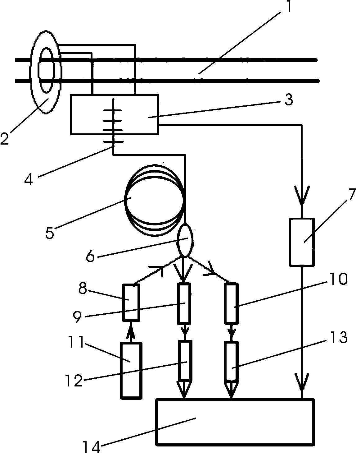
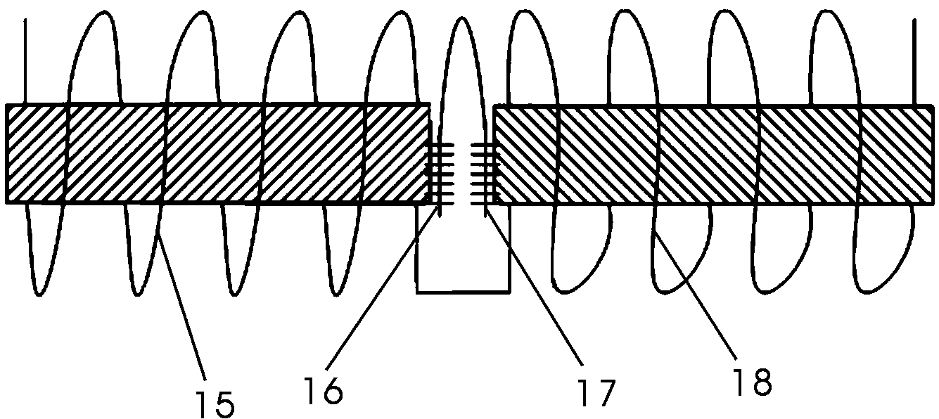
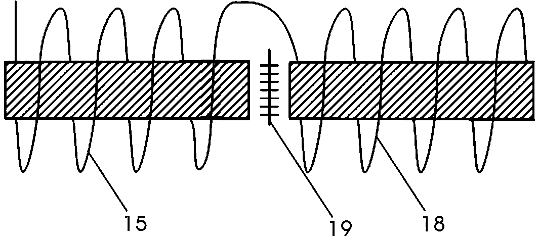
[0007] Now refer to the attached figure 1 , attached figure 2 And attached image 3 , are described as follows in conjunction with the embodiments: the self-induction photoelectric hybrid current transformer of the present invention includes a current bus 1, a precision Rogowski coil 2, a double solenoid 3 with an iron core, an optical fiber grating 4, an optical fiber 5, and an optical fiber coupling 6, optical fiber vibration sensor 7, optical fiber isolator 8, wavelength demodulator A9, wavelength demodulator B10, multi-wavelength LD light source 11, photodetector A12, photodetector B13, signal processing unit 14, with iron core Solenoid A15, Fiber Bragg Grating A16, Fiber Bragg Grating B17, Solenoid with Iron Core B18 and Fiber Bragg Grating C19. A precision Rogowski coil 2 is connected to the current bus 1, which is connected to the precision Rogowski coil 2, and a double solenoid 3 with an iron core is provided, and the double solenoid 3 with an iron core is connected...


PUM


Abstract

The invention relates to a self-induced photoelectric mixed current transformer, which detects the ultrahigh voltage large current by using an optical fiber sensor to detect the vibration information of two screws in a double screw spool with an iron core. The self-induced photoelectric mixed current transformer comprises a current bus, a precise Rogowski coil, a double screw spool with the iron core, an optical fiber grating, optical fiber, an optical fiber coupler, an optical fiber vibrating sensor, an optical fiber separator, a wavelength demodulator, a multi-wavelength LD (laser disc) light source, a photoelectric detector and a signal processing unit. The precise Rogowski coil is connected and arranged on the current base, and the double screw spool with the iron core is arranged on the precise Rogowski coil. The double screw spool with the iron core is further connected with the optical fiber grating and the optical fiber vibrating sensor. The optical fiber vibrating sensor is connected to the signal processing unit. The optical fiber grating is downwards connected with the optical fiber and the optical fiber coupler. The optical fiber coupler is further downwards connected to the optical fiber separator and the wavelength demodulator. The optical fiber separator is connected with the multi-wavelength LD light source downwards. The self-induced photoelectric mixed current transformer is simple in integral structure, convenient to operate, good in stability and safe, stable and reliable.

Description

technical field [0001] The invention relates to a photoelectric conversion device in the field of high-voltage electrical appliances and optical measurement, in particular to a self-induction photoelectric hybrid current transformer. Background technique [0002] As the voltage level of the power system continues to rise, the internal insulation of traditional oil-immersed current transformers is becoming more and more difficult, and there is a potential risk of accidents. In recent years, the country has proposed a plan to build a digital grid, making traditional oil-immersed The optical current transformer based on the magneto-optical Faraday effect is a multi-disciplinary theory and application technology integrating optical fiber sensing technology, photoelectric technology, nonlinear optics and advanced signal processing technology. Compared with the traditional high-voltage and large-current transformer technology, the optical current transformer has the advantages of ...

Claims


Application Information

Patent Timeline
Patent Type & Authority Patents(China)
IPC IPC(8): G01R15/24H01F38/32
Inventor 马任德闫珂柱田建祥秦文华周留柱孟祥省
Owner QUFU NORMAL UNIV
Learn More