
Gas valve pit leakage monitoring terminal

A technology for monitoring terminals and gas valve wells, which is applied to gas/liquid distribution and storage, pipeline systems, mechanical equipment, etc. It can solve problems such as threats to social public safety and public interests, high human resource costs, and ineffective early warning, etc., to achieve The effect of wide coverage, small environmental interference factors, and quick response

Inactive Publication Date: 2012-07-25
朗坤智慧科技股份有限公司
View PDF5 Cites 9 Cited by
  • Summary
  • Abstract
  • Description
  • Claims
  • Application Information

AI Technical Summary

Problems solved by technology

From a safety point of view, the gas valve well is a place where equipment is relatively dense on the entire gas pipeline network. Due to factors such as regional temperature differences, land subsidence, weld defects, long-term disrepair, pipeline corrosion, and external force damage, etc., the valve may be damaged. If the valve in the well is not well sealed or the surrounding pipeline leaks, the gas is easy to form accumulation in the valve well, and the explosion and deflagration accidents caused by this happen from time to time, especially as the gas pipeline network becomes more and more complex and the pipeline becomes longer and longer. Hidden dangers are becoming more and more prominent, seriously threatening social public safety and public interest
At present, the commonly used monitoring methods for gas valve well leakage include artificial olfactory detection, manual instrument inspection, and ground plant observation, etc., but these commonly used monitoring methods have certain disadvantages, such as: low efficiency, poor real-time performance, limited monitoring range, and high human resource costs. , unable to effectively warn, etc.

Method used


Image

  • Gas valve pit leakage monitoring terminal
  • Gas valve pit leakage monitoring terminal
  • Gas valve pit leakage monitoring terminal

Examples


Embodiment Construction

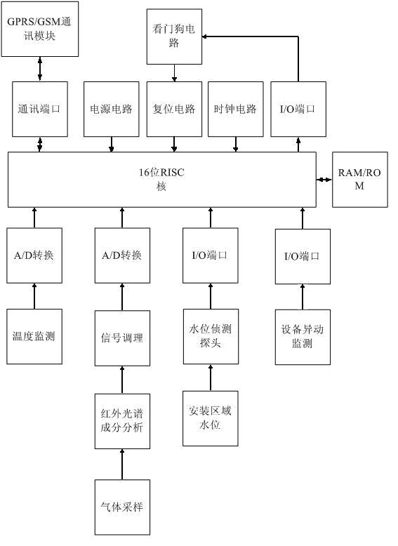
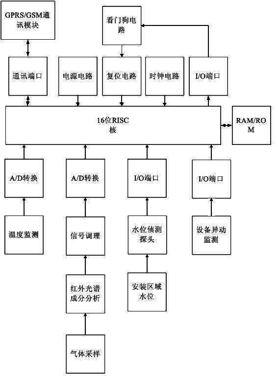
[0009] control attached figure 1 , its structure is that the equipment abnormal monitoring signal output terminal is connected to the signal input terminal of the first I / O port, the signal output terminal of the first I / O port is connected to the first signal input terminal of the 16-bit RISC core, and the installation area The water level signal output end is connected to the signal input end of the water level detection probe, the signal output end of the water level detection probe is connected to the signal input end of the second I / O port, and the signal output end of the second I / O port is connected to the 16 The second signal input terminal of the RISC core is connected, the gas signal output terminal of gas sampling is connected with the temperature signal input terminal of the infrared spectrum composition analyzer, and the temperature signal output terminal of the infrared spectrum composition analyzer is connected with the signal conditioning signal input terminal ...


PUM


Abstract

The invention relates to a gas valve pit leakage monitoring terminal, which is characterized by mainly comprising an I / O (input / output) port, a 16-bit RISC (reduced instruction set computer) core, an RAM (random access memory) / ROM (read only memory), an A / D (analog / digital) converter, a temperature monitoring signal conditioning unit, a water level detecting probe, an equipment abnormality monitor, an infrared spectral component analyzer and a mounting area water level and gas sampling unit. The gas valve pit leakage monitoring terminal has the advantages that by combining with the wireless GPRS (general packet radio service) transmission technology, low-power-consumption control technology, anti-theft alarming technology and gas leakage detecting technology, manual polling manner for preventing gas leakage of pipelines is changed into a modern automatic manner of day-and-night real-time monitoring, and accordingly, preventing and alarming capacity for leakage of the gas network of the whole city can be perfected and improved, and harm caused by gas leakage accidents is reduced. Besides, the gas valve pit leakage monitoring terminal has the advantages of high automation degree, simplicity and convenience in maintenance and repair, low cost and the like.

Description

technical field [0001] The invention relates to a gas valve well leakage monitoring terminal, which belongs to the technical field of gas valve well leakage monitoring. Background technique [0002] Among all kinds of industrial pipelines, gas pipelines are the most widely distributed high-risk pressure pipelines in the city and involve the most areas. From a safety point of view, the gas valve well is a place where equipment is relatively dense on the entire gas pipeline network. Due to factors such as regional temperature differences, land subsidence, weld defects, long-term disrepair, pipeline corrosion, and external force damage, etc., the valve may be damaged. If the valve in the well is not well sealed or the surrounding pipeline leaks, the gas is easy to form accumulation in the valve well, and the explosion and deflagration accidents caused by this happen from time to time, especially as the gas pipeline network becomes more and more complex and the pipeline becomes ...

Claims


Application Information

Patent Timeline
IPC IPC(8): F17D5/02
Inventor 武爱斌傅兵魏小庆郭钟陈龙
Owner 朗坤智慧科技股份有限公司
Learn More