
Cook top comprising at least two heating inductors

A technology for heating inductors and cooktops, applied in induction heating, induction heating control, electric/magnetic/electromagnetic heating, etc., can solve problems such as flicker and cost, and achieve the goal of avoiding flicker, avoiding humming, and reducing the number Effect

Inactive Publication Date: 2012-07-18
BSH BOSCH & SIEMENS HAUSGERAETE GMBH
View PDF5 Cites 2 Cited by
  • Summary
  • Abstract
  • Description
  • Claims
  • Application Information

AI Technical Summary

Problems solved by technology

But this method is costly and can cause problems with flicker due to voltage jumps when switching between time windows

Method used


Image

  • Cook top comprising at least two heating inductors
  • Cook top comprising at least two heating inductors
  • Cook top comprising at least two heating inductors

Examples


Embodiment Construction

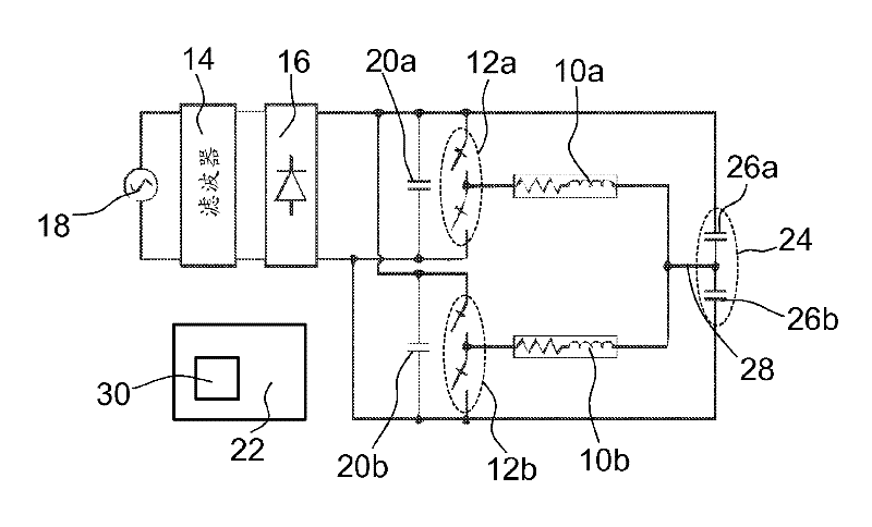
[0026] figure 1 The design of an induction hob with two heating inductors 10 a , 10 b is shown schematically, which are each connected to the output of an inverter 12 a , 12 b. The inverters 12a, 12b are supplied with direct current by a current supply unit. The current supply unit contains a filter 14 and a rectifier 16 . The filter 14 smoothes the 50 Hz alternating voltage obtained from the phase 18 of the domestic grid, which is converted to direct current by the rectifier 16 .

[0027] Between the rectifier 16 and each of the inverters 12a, 12b a damping capacitor 20a, 20b is respectively arranged, which function as a low-pass filter and prevent feedback of the high-frequency heating current generated by the inverters 12a, 12b to the home grid.

[0028] Inverters 12a, 12b are arranged in a half-bridge circuit between the two poles of the rectified supply voltage. The inverters 12 a , 12 b each consist of a pair of IGBTs or MOSFETs with self-oscillating diodes arranged ...


PUM


Abstract

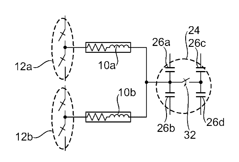
The invention relates to a cook top comprising at least two heating inductors (10a, 10b), each of which is connected to at least one resonant circuit capacitor (26a, 26b) to form a resonant circuit. In order to provide a cost-saving cook top, at least one common resonant circuit capacitor (26a, 26b) is connected to the two heating inductors (10a, 10b).

Description

technical field [0001] The invention relates to a hob with at least two heating sensors according to the preamble of claim 1 and a device for operating such a hob according to the preamble of claim 10 method. Background technique [0002] From EP 0 986 287 A2 a hob is known which has two heating inductors which are each connected in series with a separate resonant circuit capacitor. In conventional cooktops, an independent resonant circuit is usually formed for each induction heating element to be operated. In this way, the frequency and / or amplitude of the heating current can be selected independently of each other in a simple manner for the induction heating body concerned in order to adjust the heating power independently of each other. [0003] However, in order to satisfy the relevant flicker criteria and to avoid disturbing hum, in many cases adjacent heating inductors are operated with heating currents of the same frequency. However, in order to be able to achieve ...

Claims


Application Information

Patent Timeline
IPC IPC(8): H05B6/06
CPCH05B6/065H05B6/06
Inventor D.安顿法尔康C.伯纳尔鲁伊斯J.M.布尔迪奥皮尼拉J.M.德拉库尔达奥尔廷J-R.加西亚希梅内斯P.J.赫南德斯布拉斯科S.洛伦特吉尔O.卢西亚吉尔A.梅迪亚诺赫雷迪亚I.米兰塞拉诺F.蒙特德阿斯纳尔D.莫罗斯桑斯J.J.帕里西奥阿斯科纳D.普亚尔普恩特J.I.阿尔蒂加斯梅斯特雷L.A.巴拉冈佩雷斯C.卡雷特罗查马罗O.希梅内斯纳瓦斯库斯D.纳瓦罗塔伯内罗I.乌里萨帕罗奎
Owner BSH BOSCH & SIEMENS HAUSGERAETE GMBH
Learn More