
Digital laser explosion loading dynamic photoelastic experiment system

An experimental system, dynamic photoelastic technology, is applied in the direction of measuring the change force of the optical properties of the material when it is stressed, and can solve the problems of high operation and experience requirements, low experimental success rate, unfavorable research, etc., and achieve the goal of using Convenience, reliable operation, increased controllability and precision

Inactive Publication Date: 2012-07-18
CHINA UNIV OF MINING & TECH (BEIJING)
View PDF7 Cites 21 Cited by
  • Summary
  • Abstract
  • Description
  • Claims
  • Application Information

AI Technical Summary

Problems solved by technology

[0005] When working, the above two devices use traditional physical film as the recording medium, which has high requirements for the operation and experience of the experimenters, and the success rate of the experiment is low and the cost is high, which is not conducive to further research.

Method used


Image

  • Digital laser explosion loading dynamic photoelastic experiment system
  • Digital laser explosion loading dynamic photoelastic experiment system
  • Digital laser explosion loading dynamic photoelastic experiment system

Examples


Embodiment Construction

[0027] Below in conjunction with accompanying drawing, the present invention is described in further detail:

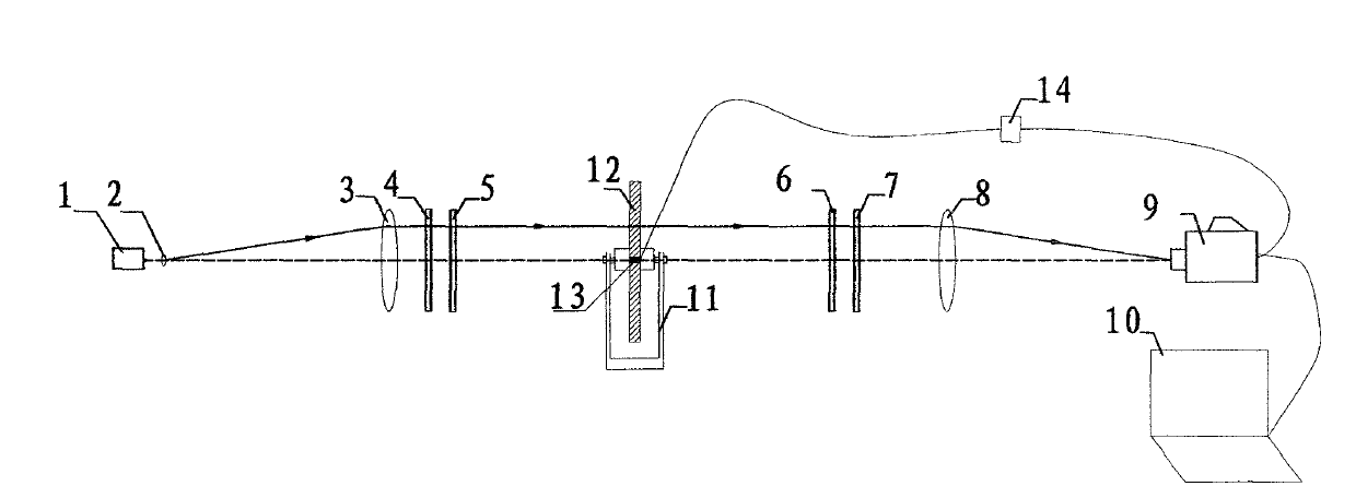
[0028] like figure 1 As shown, a digital laser explosion loaded dynamic photoelastic experiment system includes a laser 1, a beam expander 2, a front convex lens 3, a polarizer 4, a left 1 / 4 wave plate 5, a right 1 / 4 wave plate 6, a detector Polarizer 7, rear convex lens 8, explosive loading device 11, detonator 14, digital high-speed camera 9 and computer 10.

[0029] Wherein, the output end of the laser 1 corresponds to the beam expander 2 , and the beam expander 2 is located between the laser 1 and the front convex lens 3 . The front convex lens 3 in the field lens combination is responsible for converting the surface beam emitted by the beam expander 2 into a parallel beam, and then converges and transmits it through the rear convex lens 8 . Between the front and rear convex lenses 3 and 8, a polarizer 4, a left 1 / 4 wave plate 5, a right 1 / 4 wave plate 6, and an...


PUM


Abstract

The invention discloses a digital laser explosion loading dynamic photoelastic experiment system, which comprises a laser, a beam expanding mirror, a field lens combination, a left 1 / 4 wave plate, a right 1 / 4 wave plate, an analyzer, an explosion loading device, an exploder, a digital high speed video camera and a computer. The laser sends out continuous line beams which are converted into circularly polarized light through the beam expanding mirror, a field mirror and the 1 / 4 wave plate to be illuminated on a test sample of the explosion loading device, the circularly polarized light are converged through the right 1 / 4 wave plate, the analyzer and the field mirror to be illuminated into a lens of the digital high speed video camera, and finally, the circularly polarized light is exploded by the exploder and shot by starting the digital high speed video camera to form an explosion loading image. The system record and analyze the broadcast information including process of stress saves in the test sample under explosion loads, stress time and space distribution and the like, an optical path is simple, requirements for experiment environment and experiment cost are low, period is short, precision is high, and continuous observation of the whole fracture process is achieved.

Description

technical field [0001] The invention relates to a dynamic photomechanical experiment device, in particular to a digital laser explosion loading dynamic photoelastic experiment system for studying explosion stress waves. Background technique [0002] The dynamic photoelasticity experiment is an optical measurement method that uses optically sensitive materials to make a model similar to the real object, irradiates it with polarized light under the action of a dynamic load, and directly records the contour of the stress in the model on the bottom plate. It is very intuitive and can directly obtain the propagation and superposition of stress waves in solid media, as well as the instantaneous stress distribution diagram in the dynamic process of the interaction between cracks and stress waves, which can truly reflect the information and laws of the dynamic process. [0003] In the study of dynamic photoelasticity, multi-spark dynamic photoelastic instruments are usually used in ...

Claims


Application Information

Patent Timeline
Patent Type & Authority Applications(China)
IPC IPC(8): G01L1/24
Inventor 杨仁树杨立云孙强马鑫民
Owner CHINA UNIV OF MINING & TECH (BEIJING)
Learn More