
Process for production of core-shell particles, core-shell particles, and paste composition and sheet composition which contain same

A manufacturing method, particle technology, applied in printed circuit manufacturing, cable/conductor manufacturing, chemical instruments and methods, etc., can solve problems such as insulation reduction

Inactive Publication Date: 2012-07-11
TORAY IND INC
View PDF8 Cites 17 Cited by
  • Summary
  • Abstract
  • Description
  • Claims
  • Application Information

AI Technical Summary

Problems solved by technology

However, the dispersed metal particles in the insulating material will re-agglomerate and join together, forming channels (passes) of the metal particles in the insulating material, and thus the insulation may be reduced.

Method used


Image

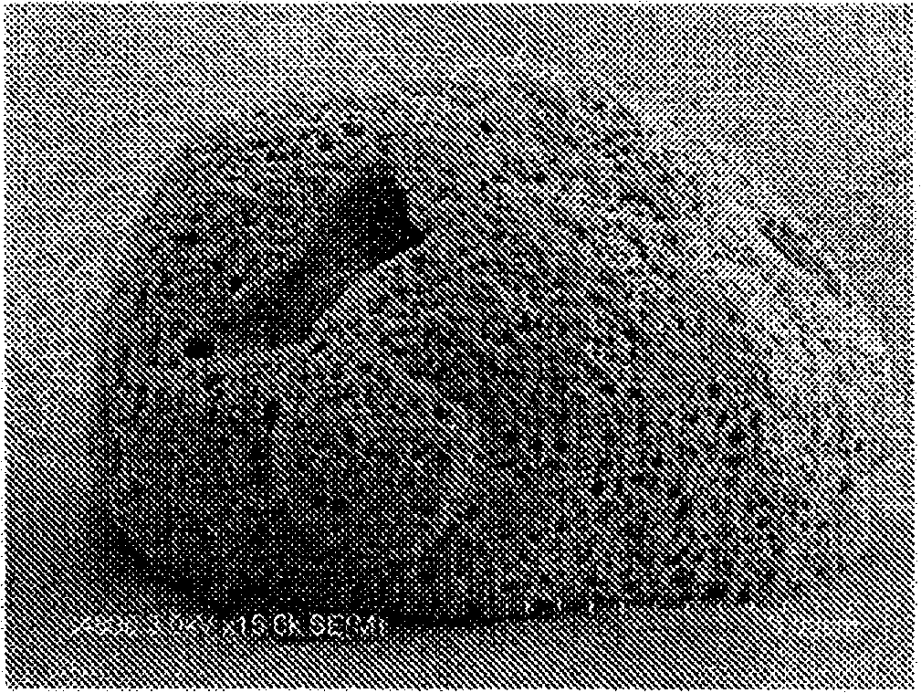
  • Process for production of core-shell particles, core-shell particles, and paste composition and sheet composition which contain same
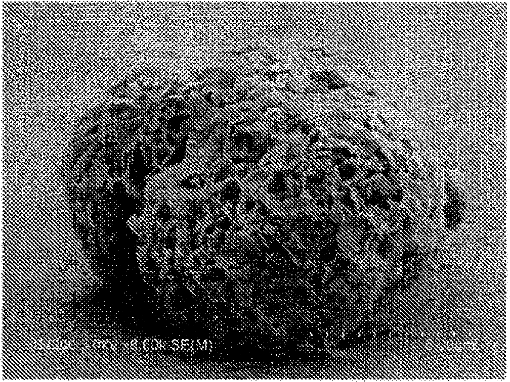
  • Process for production of core-shell particles, core-shell particles, and paste composition and sheet composition which contain same
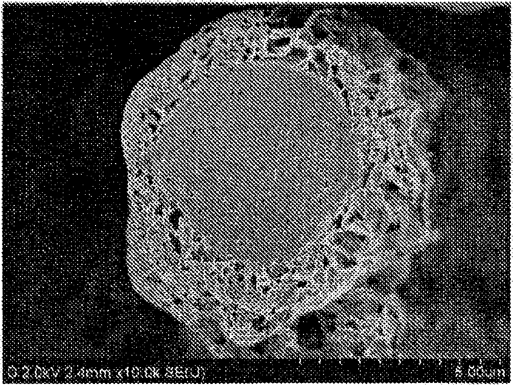
  • Process for production of core-shell particles, core-shell particles, and paste composition and sheet composition which contain same

Examples


Embodiment 1

[0131] An acidic organic substance "resin A", THFA, and a silane coupling agent "KBM503" were mixed at a weight ratio of 10:90:1 to prepare a layer-forming mixture. Next, 1 drop of the prepared mixture was dropped on the silicon substrate on which the copper film was formed on the surface by the sputtering method using a dropper, and the substrate was heated on a hot plate at 90° C. for 1 hour. After immersing the heated substrate in acetone for 30 seconds, it was washed with ultrapure water and dried at 90° C. for 15 minutes. It was confirmed that a layer was formed on the dried substrate.

[0132]Furthermore, a silicon substrate with a silver film formed on its surface by a sputtering method, a silicon substrate with a gold film formed on its surface by a sputtering method, a silicon substrate with a tin film formed on its surface by a sputtering method, an aluminum plate, a stainless steel plate, A zinc plate and a solder (tin: 60%, lead: 40%) plate were used as substrates...

Embodiment 2

[0136] After mixing and stirring 10 g of copper particles "MA-C08J", 10 g of ultrapure water, and 0.1 g of silane coupling agent "KBM603", transfer the mixture to an aluminum cup, let the cup stand still to settle the copper particles, and remove the Clear liquid, and then heat treatment at 100°C for 1 hour to pre-treat copper particles.

[0137] 0.1 g of phosphoric acid and 5 g of ultrapure water were mixed and stirred to prepare a mixture for layer formation. In addition, the pH of the aqueous solution which mixed 0.1 g of phosphoric acid and 9.9 g of ultrapure water (it describes as "1 weight% aqueous solution" in a table|surface. The following is the same) was 1.8. For pH measurement, a pH meter "CyberScan pH310" (manufactured by EUTECH INSTRUMENTS) was used.

[0138] Next, the mixture for layer formation was put into a 100 ml eggplant-shaped flask, and 10 g of the above-mentioned pretreated copper particles (mixed amount of metal particles: 18% by volume) were added, and...

Embodiment 3

[0143] The copper particles were not pretreated with a silane coupling agent, and core-shell particles and a paste-like metal particle-dispersed insulating material were produced in the same manner as in Examples. The evaluation results are listed in Table 2. In addition, the SEM images of core-shell particles are shown in Figure 5 . Compared with the core-shell particles produced in Example 2, the mesh of the shell is coarser.


PUM

PropertyMeasurementUnit
particle sizeaaaaaaaaaa
thicknessaaaaaaaaaa
particle sizeaaaaaaaaaa

Abstract

Disclosed is a process which comprises bringing an acidic organic substance or phosphoric acid into contact with a metal to form, on the surface of the metal, a layer that contains either an organic acid salt formed from both the acidic organic substance and the metal or a phosphoric acid salt formed from both the phosphoric acid and the metal. In the process, the layer can be selectively formed only on the surface of the metal. When the process is applied to the production of core-shell particles, neither agglomeration of the particles nor viscosity increase of the fluid occurs, while when the process is applied to the production of a covered metal-wiring circuit board, the layer can be selectively formed only in the metal area to be covered.

Description

technical field [0001] The present invention relates to a technique for coating a metal surface such as metal particles or metal wiring with a layer. More specifically, it relates to a technique of bringing an acidic organic substance or phosphoric acid into contact with a metal to form a layer containing an organic acid salt or a phosphate on the surface of the metal. [0002] In addition, the present invention relates to metal particles covered with a coating layer (shell), and an insulating material having high thermal conductivity or high magnetic permeability obtained by dispersing the metal particles, and a coating material for metal wiring or metal joints on a circuit board. . Background technique [0003] As the density, frequency, and performance of components such as ICs, lasers, and LEDs in electronic devices such as mobile phones and personal computers increase, the local heat generated by these components is gradually increasing, and heat radiation countermeasu...

Claims


Application Information

Patent Timeline
Patent Type & Authority Applications(China)
IPC IPC(8): C08F2/00B32B15/08C09C1/62C09C3/10C23C22/08H05K3/28H05K9/00
CPCH05K2203/122H05K2201/0224C09C3/10C01P2004/84C01P2006/40H05K2201/10977C01P2004/03C01P2004/62H05K3/28C09C1/62C09C1/64C09C1/644Y10T428/2991B22F1/16B32B15/02C23C22/07H05K3/22C08L101/00C08K9/10B01J13/04H01B13/00H01B5/00H01B1/22H01B1/20
Inventor 榛叶阳一新关彰一野中敏央
Owner TORAY IND INC
Learn More