
Intermediate infrared femtosecond mode-locked laser

A mode-locked laser and femtosecond technology, applied in lasers, laser components, semiconductor lasers, etc., can solve problems such as increasing the difficulty of stable mode-locking, sensitive adjustment accuracy, and increasing laser power thresholds

Inactive Publication Date: 2012-07-11
SHANGHAI JIAO TONG UNIV
View PDF5 Cites 12 Cited by
  • Summary
  • Abstract
  • Description
  • Claims
  • Application Information

AI Technical Summary

Problems solved by technology

However, limited by the mode-locking technology and detection technology of the 2-3um band, there are still many problems in the mode-locking of the 2-3um band laser. The adjustment accuracy is very sensitive, and it also greatly increases the output laser power threshold for stable mode-locking; on the other hand, although the semiconductor saturable absorbing mirror (SESAM) technology for mode-locking in the near-infrared band is very mature, it has already been applied to commercialization In lasers, but in the mid-infrared band, there are still many problems with SESAM for solid-state mode-locked lasers. At the same time, the high saturation energy flow requirements of SESAM also increase the difficulty of achieving stable mode-locking in the 2um band.

Method used


Image

  • Intermediate infrared femtosecond mode-locked laser
  • Intermediate infrared femtosecond mode-locked laser

Examples


Embodiment Construction

[0016] The present invention will be further described below in conjunction with the embodiments and accompanying drawings, but the protection scope of the present invention should not be limited thereby.

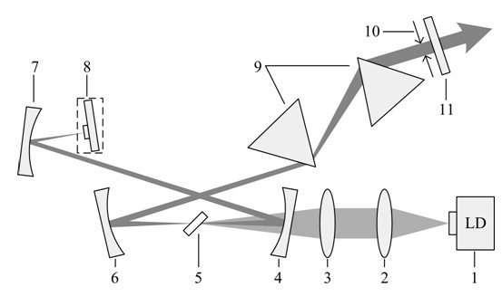
[0017] see figure 1 , figure 1 It is the mid-infrared femtosecond mode-locked laser of the present invention. As shown in the figure, the pump light emitted by the laser diode 1 is collimated and focused by the collimating mirror 2 and the focusing mirror 3, and then focused to the thulium-calcium-doped lithium-niobium-gallium through the input spherical mirror 4 In the garnet crystal (Tm:CLNGG5), the number of particles is reversed and the laser oscillation is formed in the laser cavity. The laser in the laser resonator is reflected by the input spherical mirror 4 to the spherical high-reflective focusing mirror 7, the laser is focused on the graphene mode-locking element 8 through the spherical high-reflective focusing mirror 7, and then returns along the original path, ...


PUM


Abstract

The invention relates to an intermediate infrared femtosecond mode-locked laser which comprises a collimating mirror, a focusing mirror, an input spherical surface mirror, a laser medium and a spherical surface high-reflection mirror which are sequentially arranged along a direction of a pumping light beam outputted by a laser diode, wherein lasers in a five-mirror laser resonance cavity formed by the input spherical surface mirror, the spherical surface high-reflection mirror, the spherical surface high-reflection focusing mirror, an output coupling mirror and a graphene mode-locking element is reflected onto the high-reflection focusing mirror through the input spherical surface mirror, is focused on the graphene mode-locking element, returns back along the original path by sequentially passing through the spherical surface high-reflection focusing mirror, the input spherical surface mirror, a laser crystal and the spherical surface high-reflection mirror, is deflected and reflected to a dispersion compensation prism pair by the spherical surface high-reflection mirror, and is output from the output coupling mirror through a slit. According to the intermediate infrared femtosecond mode-locked laser, graphene growing by adopting a CVD (Chemical Vapor Deposition) method is transferred to a laser wavelength high-reflection mirror, and is protected by using inert gas, and thus stable mode-locked laser pulse output is realized in an intermediate infrared band. The intermediate infrared femtosecond mode-locked laser has the advantages of being simple in regulation, low in manufacture cost, and easy to realize single layer (little non-saturated loss).

Description

technical field [0001] The invention relates to a mid-infrared solid-state laser, in particular to a mid-infrared femtosecond mode-locked laser. Background technique [0002] Thanks to the development of laser materials such as titanium sapphire and mode-locking technology in the 1980s, the current ultrafast laser generation technology in the 0.8-1.0 μm band is very mature, and commercial products in this band continue to emerge. However, with the continuous development of physics, it has been found that many ultrafast laser-matter interaction processes are closely related to the laser wavelength, so expanding the wavelength coverage of ultrafast lasers has become a new challenge today. The 2-3 micron near-mid-infrared laser band is adjacent to the 1 μm band, which is currently the most mature mode-locked laser technology. There are very important potential applications in fields such as machining. However, limited by the mode-locking technology and detection technology of...

Claims


Application Information

Patent Timeline
IPC IPC(8): H01S3/098H01S3/0941
CPCH01S3/1118H01S3/0811H01S5/065H01S3/0805H01S3/09415
Inventor 谢国强马杰高文兰钱列加吕鹏
Owner SHANGHAI JIAO TONG UNIV
Learn More