
Combustion device for preheating and combusting sprayed-up backflow on nozzle with uniform mixing and distribution of coal gas and air

A combustion device and a technology of returning a combustion chamber, which are applied in the combustion using lump fuel and gaseous fuel, the combustion using liquid fuel and gaseous fuel, the combustion using gaseous fuel and powder fuel, etc., can solve the problem of low combustion temperature and low heat. Problems such as unstable combustion of gas and weak combustion intensity

Inactive Publication Date: 2012-07-11
ZHENGZHOU YUXING REFRACTORY MATERIAL
View PDF5 Cites 2 Cited by
  • Summary
  • Abstract
  • Description
  • Claims
  • Application Information

AI Technical Summary

Problems solved by technology

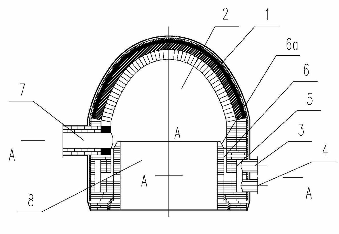
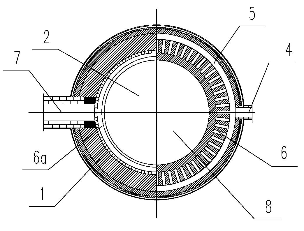
[0005] When using this combustion device, the gas and air are quickly mixed through the premixing ring, and the premixing nozzles uniformly distributed on the inner wall of the ring bend upward through the premixing guide ring groove and enter the return combustion chamber to complete the full premixing The gas is preheated by the recirculated high-temperature flue gas, and then burns quickly and stably in a concentrated manner, thus effectively solving the key problems of unstable combustion, weak combustion intensity, and low combustion temperature of low calorific value gas; The long-flame combustion mode that takes up a lot of combustion space is changed to the rapid and high-intensity combustion mode of recirculation preheating premixed airflow

Method used


Image

  • Combustion device for preheating and combusting sprayed-up backflow on nozzle with uniform mixing and distribution of coal gas and air
  • Combustion device for preheating and combusting sprayed-up backflow on nozzle with uniform mixing and distribution of coal gas and air
  • Combustion device for preheating and combusting sprayed-up backflow on nozzle with uniform mixing and distribution of coal gas and air

Examples


Embodiment Construction

[0008] The specific implementation manners of the present invention will be described in detail below in conjunction with the accompanying drawings.

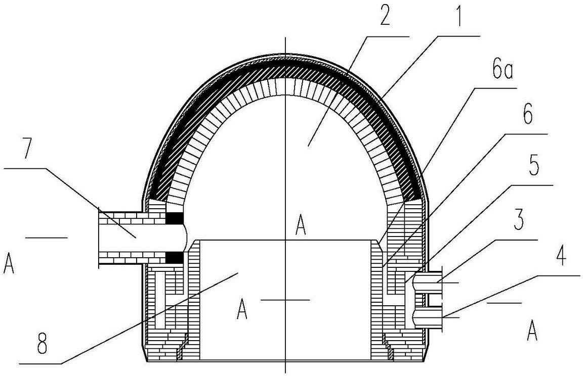
[0009] Such as figure 1 , figure 2 As shown, the present invention includes a combustion chamber wall 1, a recirculation combustion chamber 2, a gas intake pipe 3, an air intake pipe 4, a premixed ring 5 for gas and air, a premixed gas nozzle 6, and a premixed gas guide ring groove 6a , the airflow outlet pipe 7 and the combustion device airflow outflow section 8, the combustion chamber wall 1 is composed of the spherical vault above and the cylinder below, and the upper space of the combustion chamber wall is the backflow combustion chamber 2. A gas inlet pipe 3 and an air inlet pipe 4 are arranged perpendicular to the axis of the cylinder of the chamber wall 1, and the gas inlet pipe and the air inlet pipe are vertically or obliquely connected to the premixing ring 5 built in the combustion chamber wall 1 , the section of t...


PUM


Abstract

The invention relates to a combustion device for preheating and combusting sprayed-up backflow on a nozzle with uniform mixing and distribution of coal gas and air. The combustion device effectively solves the problems such as low mixing speed, non-uniform mixing, low combustion intensity, incomplete combustion, complex space of a combustion chamber and complex structure of a combustor, The combustion device is characterized in that the upper space of a wall body of the combustion chamber is a backflow combustion chamber; a coal-air inlet pipe on the wall body of the combustion chamber is connected with a premixing ring road; a premixed gas nozzle at the middle part of the premixing ring road is connected with a premixed gas guiding ring groove which is arranged at the bottom part of the backflow combustion chamber; a gas flow outlet pipe is arranged on the ring wall of the side surface of the wall body of the combustion chamber or the top part of a sphere-shaped arch; and the lower part of the backflow combustion chamber is provided with a gas flow outflow section. The combustion device effectively solves the key problems such as instable combustion, weak combustion intensity and low combustion temperature at low calorific value, improves the thermo-engineering property of a hot-air furnace and an industrial kiln, and plays a decisive role in realizing high efficiency, high air temperature, energy conservation and environmental protection of the hot-air furnace and the industrial kiln.

Description

technical field [0001] The invention relates to a combustion device used for blast furnace hot blast stove (or industrial kiln) and spraying backflow preheating combustion on the uniformly distributed nozzle of gas and air mixing. Background technique [0002] At present, from the perspective of energy saving and consumption reduction, blast furnace hot blast stoves are required to obtain high performance and high benefits under the combustion of low calorific value blast furnace gas, and finally achieve the goals of high efficiency, energy saving, environmental protection, and increased production. For this reason, completing the intensified combustion process and efficient heat transfer process in the hot blast stove and combining them organically is a necessary condition to achieve the above goals, which involves the performance of the combustion device, the structure and arrangement of the heat storage body, and Organization of the air flow field. Looking at the various...

Claims


Application Information

Patent Timeline
IPC IPC(8): F23C3/00F23C5/08
Inventor 陈维汉刘辉凯
Owner ZHENGZHOU YUXING REFRACTORY MATERIAL
Learn More