
Coal pyrolysis system and pyrolysis method

A coal pyrolysis and coal heat technology, applied in the coal pyrolysis system and the field of pyrolysis, can solve the problems of harsh operating conditions, high equipment investment costs and high operating costs, and achieve higher productivity, lower investment costs and lower costs. Effect

Inactive Publication Date: 2012-07-11
SHENWU TECH GRP CO LTD
View PDF2 Cites 9 Cited by
  • Summary
  • Abstract
  • Description
  • Claims
  • Application Information

AI Technical Summary

Problems solved by technology

However, in the prior art, there are problems such as low tar yield during coal pyrolysis
Although the hydropyrolysis process can increase the tar yield, in the hydropyrolysis process, pure hydrogen is used as the reaction gas, the hydrogen production process is complex, the equipment investment cost is large, the operating conditions are harsh, and the operating cost is high

Method used


Image

  • Coal pyrolysis system and pyrolysis method
  • Coal pyrolysis system and pyrolysis method

Examples


Embodiment 1

[0031] The coal pyrolysis method of the present embodiment comprises the following steps:

[0032] (1) After drying and preheating, the raw coal enters the coal pyrolysis reactor for pyrolysis reaction, the reaction temperature is 700°C, and the pressure is 1.5Mpa;

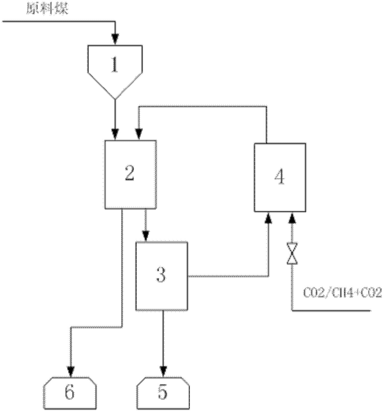
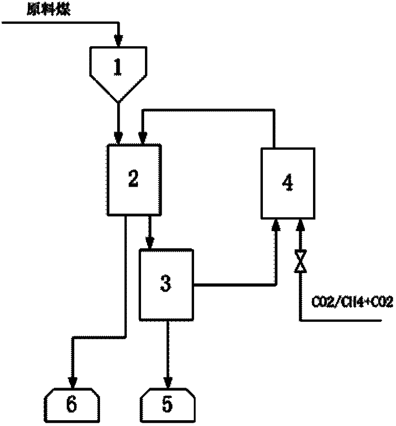
[0033] (2) The coal pyrolysis gas from the pyrolysis reactor enters the coal pyrolysis gas cooling and gas-liquid separation system for cooling and separation. The cooling and gas-liquid separation part adopts frozen brine at -10°C for heat exchange; After gas separation, the tar and water are separated by centrifugation, and the tar is collected; after the separated coal pyrolysis gas fan is pressurized, additional carbon dioxide is introduced into the coal pyrolysis gas catalytic activation system filled with catalysts for catalytic activation. / Al 2 o 3 Catalyst (preparation by impregnation method, Ni mass content is 11.2%, uses H before use 2 -N 2 Reduction at 750°C for 2 hours in a mixed gas), and catalyt...

Embodiment 2

[0040] Same as above-mentioned Example 1, the mixed gas of methane and carbon dioxide is supplemented during the reaction, and the volume content of methane in the mixed gas is 50%.

Embodiment 3

[0046] The experimental reaction was carried out on a small batch coal pyrolysis reaction device. The device can handle 20 kg of coal in a single batch. Coal pyrolysis gas activation in Ru / Al 2 o 3 Catalyst (preparation by impregnation method, Ru mass content is 0.59%, uses H before use 2 -N 2 Reduction in the mixed gas at 750°C for 2 hours) is carried out on a fixed bed, and carbon dioxide is supplemented by detecting the pressure of the system (when the pressure drops, the pressure of the entire system is restored by supplementing the gas). The cooling and gas-liquid separation part uses -10°C frozen brine for heat exchange. The separated mixed gas is pressurized by the fan and sent to the fixed bed reactor filled with catalyst for activation. The collected tar and water mixture is separated from oil and water by centrifugation. Pyrolysis conditions: temperature 700°C, reaction time 5 hours, pressure 1.5MPa, tar and semi-coke yields were calculated by weighing.


PUM


Abstract

The invention provides a coal pyrolysis system and pyrolysis method for improving tar yield. The coal pyrolysis system comprises a coal pyrolysis reactor, a coal drying and preheating system connected with the coal pyrolysis reactor and a gas catalytic activation system for activating the coal pyrolysis reaction gas, wherein the gas outlet of the gas catalytic activation system is communicated with the coal pyrolysis reactor. According to the coal pyrolysis system and pyrolysis method, the yield of tar from the coal pyrolysis is improved by carrying out catalytic activation on the reaction gas; the circulating coal pyrolysis gas or the coal pyrolysis gas supplemented with carbon dioxide or a mixture of carbon dioxide and methane is used as the coal pyrolysis reaction gas after catalytic activation, thus the gas generated by the coal pyrolysis is sufficiently utilized, a great amount of hydrogen is not needed to be added to be used as the reaction gas, and the coal pyrolysis cost is lowered.

Description

technical field [0001] The invention relates to a coal pyrolysis system and a pyrolysis method thereof, in particular to a coal pyrolysis system and a pyrolysis method for coal pyrolysis using activated coal pyrolysis gas. Background technique [0002] Since the 21st century, the rapid economic growth has led to a sharp increase in the demand for chemical raw materials in the whole society. In the structure of chemical raw materials, coal accounts for more than half. consensus. In order to realize the graded and efficient utilization of coal resources, the academic community has proposed a process idea of ​​"coal topping", which fully extracts gases, liquid fuels and fine chemicals from coal. [0003] Coal is the main energy source in our country. The coal pyrolysis process is to extract the hydrogen-rich components in the coal in the form of liquid and gas under relatively mild conditions before the coal is used by gasification, combustion or other methods, so as to impro...

Claims


Application Information

Patent Timeline
IPC IPC(8): C10B57/00C10B57/08C10B57/10C10K1/00C10K1/04
Inventor 吴道洪史雪君
Owner SHENWU TECH GRP CO LTD
Learn More