
Synchronization control device of deceleration direct-current motor

A DC motor, synchronous control technology, applied in the direction of DC motor speed/torque control, control of multiple DC motors, excitation or armature current control, etc. , to achieve the effect of improving the speed control performance

Inactive Publication Date: 2012-07-04
CMECH (GUANGZHOU) INDUSTRIAL LTD
View PDF5 Cites 14 Cited by
  • Summary
  • Abstract
  • Description
  • Claims
  • Application Information

AI Technical Summary

Problems solved by technology

However, since the DC motor adopts an open-loop control system, the controller of the DC motor cannot monitor the actual speed of the motor shaft. In addition, in the above products, some products are equipped with a gearbox in the direction of the DC motor shaft in order to reduce the final output speed. Due to the error introduced by the transmission, there is often a certain distance between the actual output speed of the motor and the expected speed. Taking a 12-volt DC motor as an example, when it operates with a 12-volt voltage, the maximum difference in the speed of different DC motors is about 20%. As a result, the performance of different terminal products based on the same model may vary greatly, which affects the use effect of the product
In practice, a problem encountered by users is that when several electric hollow louver glass products of the same height run up and down at the same time, the horizontal relative positions of the lower beams will be staggered, and the staggered distance will become larger as the running time increases, which seriously affects the perception

Method used


Image

  • Synchronization control device of deceleration direct-current motor
  • Synchronization control device of deceleration direct-current motor

Examples


Embodiment Construction

[0018] Referring to accompanying drawing below, the present invention will be further described:

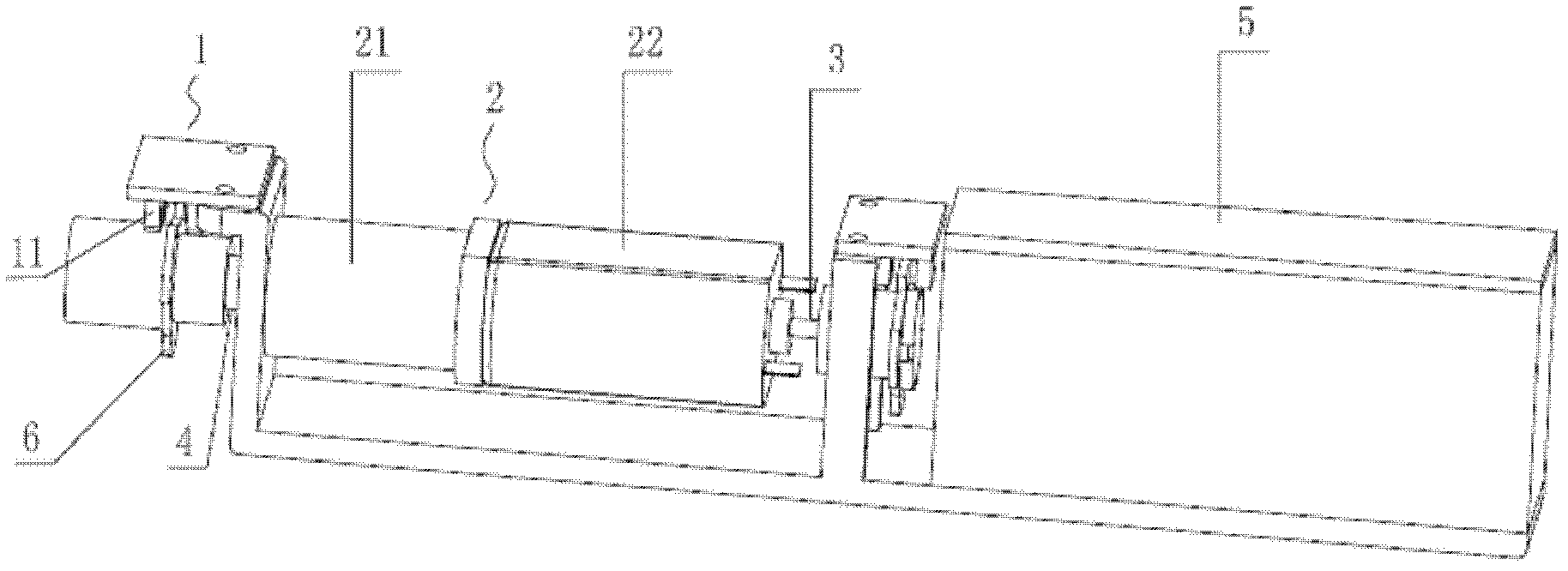
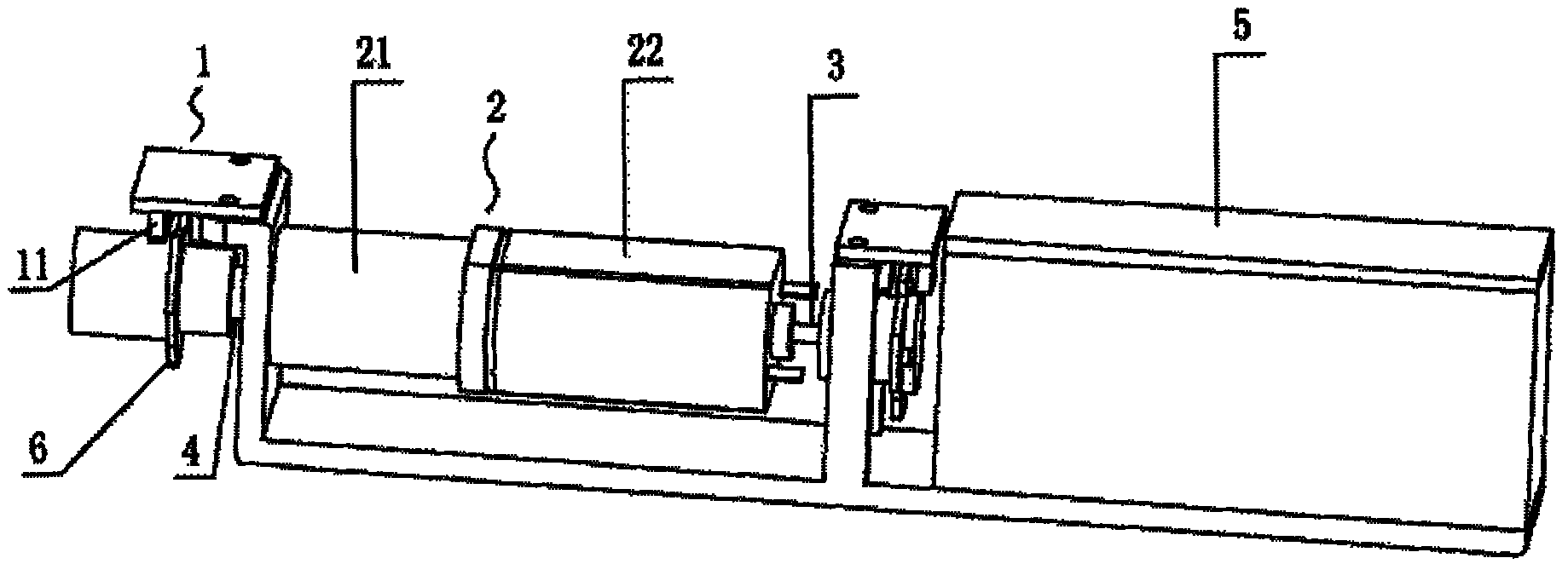
[0019] see figure 1 , the synchronous control device of the deceleration DC motor of the present invention comprises a deceleration DC motor 2 and a controller 5, the deceleration DC motor 2 includes a motor main body 22 and a reduction box 21, and the deceleration DC motor 2 is provided with a device for monitoring The speed measurement module 1 of the current speed of the motor shaft, the controller 5 is provided with a storage unit for storing the reference speed of the motor shaft, the speed measurement module 1 is connected to the controller 5, when the current speed of the deceleration DC motor 2 is different from the reference speed At the same time, the controller 5 changes the input voltage of the deceleration DC motor 2 . In this embodiment, the speed measurement module 1 includes an opaque fan blade 6 arranged on the motor shaft and a detection unit for detecting the ...


PUM


Abstract

The invention relates to a synchronization control device of a deceleration direct-current motor, which comprises a deceleration direct-current motor and a controller, wherein the deceleration direct-current motor comprises a motor main body and a speed reduction box, a speed measurement module for monitoring the current rotating speed of a rotating shaft of the motor is arranged on the deceleration direct current motor, the controller is internally provided with a storage unit for storing a reference rotating speed of the rotating shaft of the motor, the speed measurement module is connected with the controller, and when the current rotating speed of the deceleration direct-current motor is different from the reference rotating speed, the controller changes the size of the input voltage of the deceleration direct-current motor. According to the invention, the speed measurement module forming a closed loop circuit with the controller is arranged on the deceleration direct-current motor, so that the controller can be used for monitoring the current speed of the rotating shaft of the motor and immediately regulating the input voltage of the deceleration direct-current motor, thus the speed control performance of the deceleration direct-current motor is greatly improved; and synchronization action can be realized by using a plurality of electric curtains of the synchronization control device.

Description

technical field [0001] The present invention relates to a control device for a DC motor, and more particularly, to a synchronous control device for a geared DC motor. Background technique [0002] Because of its simple structure, low cost, and easy manufacturing and control, DC motors are widely used in daily life that does not require high precision, such as printers, scanners, electric curtains and other products. The size of the input voltage controls the running speed of the motor shaft. If the input voltage remains constant, the speed of different DC motors will vary by about 20%, and the speed of the same motor will vary with the load. However, since the DC motor adopts an open-loop control system, the controller of the DC motor cannot monitor the actual speed of the motor shaft. In addition, in the above products, some products are equipped with a gearbox in the direction of the DC motor shaft in order to reduce the final output speed. Due to the error introduced by ...

Claims


Application Information

Patent Timeline
IPC IPC(8): H02P7/06H02P5/68
CPCH02P7/06H02P7/2855H02P5/68
Inventor 刘力松
Owner CMECH (GUANGZHOU) INDUSTRIAL LTD
Learn More