
rectifier motor

A technology of electric motors and rectifiers, applied in the direction of electric components, electrical components, electromechanical devices, etc., can solve the problems of reduced service life and large tolerances of robustness, and achieve the effect of small tolerances, simple methods and methods, and more robust guidance

Inactive Publication Date: 2018-01-26
ROBERT BOSCH GMBH
View PDF4 Cites 0 Cited by
  • Summary
  • Abstract
  • Description
  • Claims
  • Application Information

AI Technical Summary

Problems solved by technology

[0003] A disadvantage of the prior art is that the brush holders are designed as rectangular carbon cartridges with relatively large tolerances for the associated brush coverage of the carbon brushes to the current collectors, so that the ripple current signal generated by the rectification has only a limited robustness
This limited robustness further decreases over the service life of the carbon brushes, so that correspondingly the ripple current signal generated during commutator motor operation can only be used to a limited extent for precise determination of the rotational position of the rotor

Method used


Image

  • rectifier motor
  • rectifier motor
  • rectifier motor

Examples


Embodiment Construction

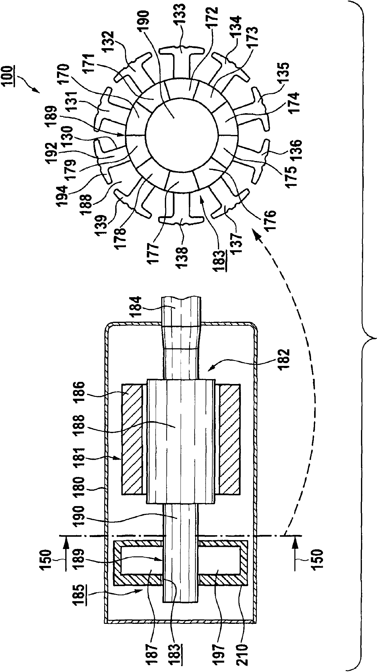
[0054] figure 1 Shown is a commutator motor 100 according to one embodiment with stator and rotor parts 181 and 182 , which has a motor shaft 184 which is exemplarily mounted in a motor housing 180 and which can, for example, be Used, for example, as drive shafts for electric window regulators in automobiles. The stator part 181 has, for example, permanent magnets 186 , and the rotor part 182 has, for example, a rotor core or iron core 188 .

[0055] Commutator motor 100 has a commutator 185 with a defined commutator diameter for commutation, which can be controlled or regulated so that not only reverse rotation but also a desired speed can be specified. The working principle and structure of a suitable commutator motor can be fully understood from the prior art, so no further elaboration will be made here for the sake of brevity.

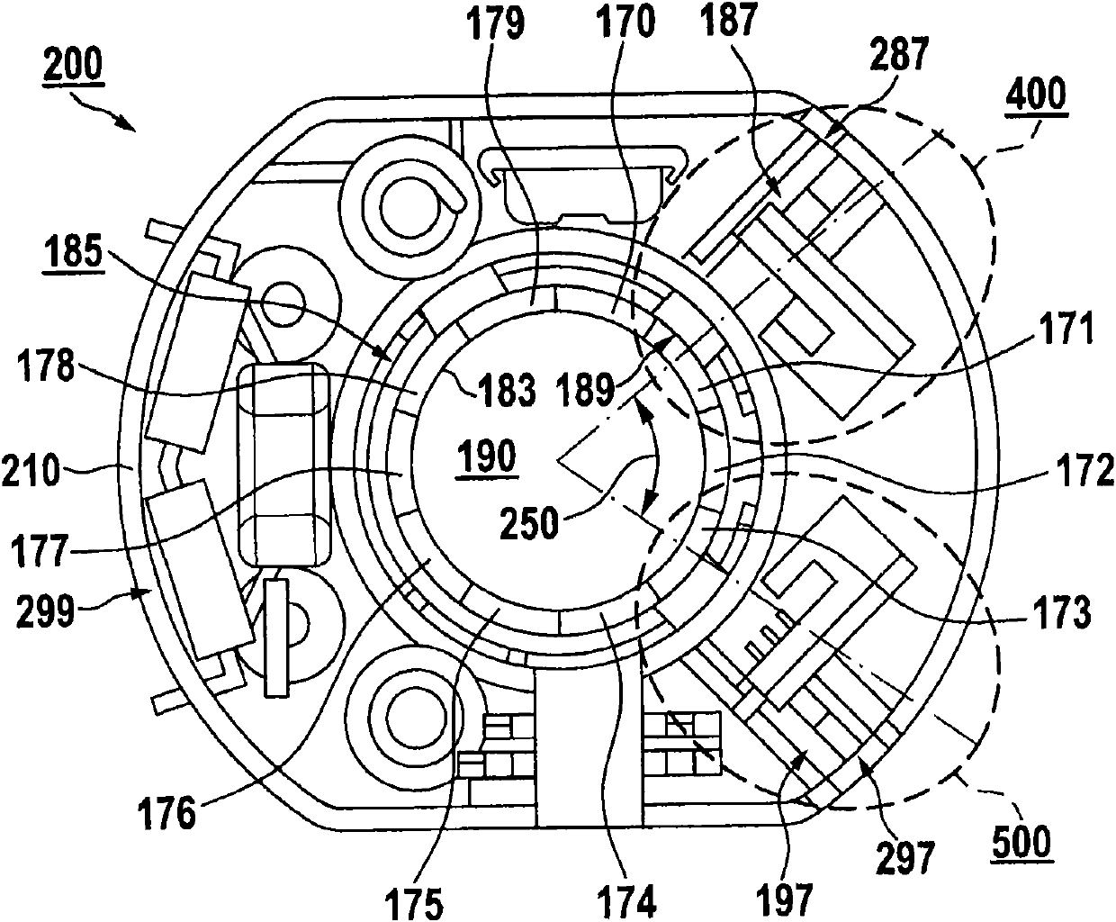
[0056]The rectifier 185 exemplarily includes a current collector 183 which forms sliding contact with two or more brushes 187, 197 on an associa...


PUM


Abstract

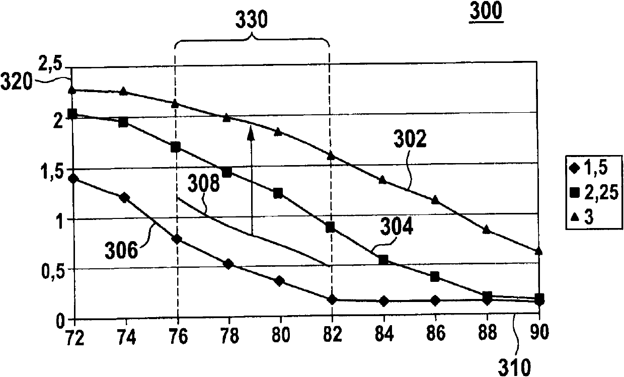
The motor (100) has a commutator (185) comprising a stationary collector (183) and associated carbon brushes (187, 197) that are in sliding contact with a collecting bearing surface (189). The brushes are arranged in association with cottage-like brush holders i.e. sliding guide. The brush holders are adapted to allow an arrangement of the brushes at an angle of 72 to 108 degrees with respect to a predetermined brush angle of 79 degrees. Width of the brushes is in a range of 1.8-3 mm. The brush holders are formed on an injection-molded part.

Description

technical field [0001] The invention relates to a commutated electric motor with a commutator having a current collector in sliding contact with an associated brush on the current collector running surface, the brush being mounted in an associated brush holder. Background technique [0002] Commutated motors having a rectifier designed for commutation are known from the prior art. It has a current collector in sliding contact with the associated brush on the collector working surface. Brushes, such as carbon brushes and current collectors, deliver the motor current necessary for operation of the commutated motor. The commutation of such commutated motors produces a so-called "ripple current" which can be used to determine the corresponding rotational position of the motor. [0003] A disadvantage of the prior art is that the brush holders are designed as rectangular carbon cartridges with relatively large tolerances for the associated brush coverage of the carbon brushes t...

Claims


Application Information

Patent Timeline
Patent Type & Authority Patents(China)
IPC IPC(8): H02K5/14H02K13/00
CPCH02K5/148H02K13/10H02K23/66H02K2213/03
Inventor D·劳克
Owner ROBERT BOSCH GMBH
Learn More