
Ceramic dielectric annular capacitor

A ring capacitor and ceramic dielectric technology, applied in the field of capacitors, can solve the problems of low utilization efficiency of space volume, inability to adapt to high-voltage power supply occasions, and inability to solve the problems of the size of the capacitor material, the size of the creepage, the size of the capacitor capacity, etc. The effect of electric capacity, improving volume utilization rate and compact structure

Inactive Publication Date: 2012-07-04
珠海威瀚科技发展有限公司
View PDF2 Cites 15 Cited by
  • Summary
  • Abstract
  • Description
  • Claims
  • Application Information

AI Technical Summary

Problems solved by technology

At the same time, the capacitor is also matched with other components, and the utilization efficiency of the space volume is low. The above defects put forward new requirements for the development and improvement of the capacitor.
For example, the ring capacitor 0820179476.6 adopts a ring three-dimensional structure, but both electrodes are on the inner ring surface, which cannot solve the contradiction between the volume size of the capacitor material and the creepage distance between the two electrodes and the capacitor capacity, and cannot be adapted to high-voltage power-taking occasions

Method used


Image

  • Ceramic dielectric annular capacitor
  • Ceramic dielectric annular capacitor
  • Ceramic dielectric annular capacitor

Examples


Embodiment Construction

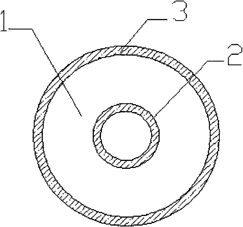
[0012] refer to figure 1 and figure 2 , a ceramic dielectric ring capacitor, comprising a dielectric ceramic body 1, the dielectric ceramic body 1 is a cylindrical structure with a hole in the middle, and is characterized in that: it also includes an inner ring arranged on the inner ring surface of the dielectric ceramic body 1 The lead ring 2 and the outer lead ring 3 arranged on the outer surface of the dielectric ceramic body 1, the inner lead ring 2 and the outer lead ring 3 are isolated from each other.

[0013] As a preferred embodiment of the present invention, the inner lead ring 2 and the outer lead ring 3 are staggered from each other, and an insulating section is formed between them.

[0014] One pole of the ceramic dielectric ring capacitor is set on the inner lead ring 2 on the inner ring surface of the ceramic medium, and the other pole is set on the outer lead ring 3 on the outer surface of the ceramic medium, from figure 1 It can be seen from the figure that...


PUM


Abstract

The invention relates to a ceramic dielectric annular capacitor. The capacitor comprises a dielectric ceramic body 1 which has a cylindrical structure with a middle through hole, and is characterized by also comprising an inner lead ring 2 arranged on the inner ring surface of the dielectric ceramic body, and an outer lead ring 3 arranged on the outer side surface of the dielectric ceramic body, wherein the inner lead ring 2 and the outer lead ring 3 are isolated and staggered from each other, and an insulation section is formed between the inner lead ring 2 and the outer lead ring 3; and a clamping groove 4 is formed at the bottom of the inner ring surface of the dielectric ceramic body 1. The capacitor effectively solves the problem that the influence of a distance between pole plates of a cylindrical high-voltage ceramic capacitor on capacity and a creepage distance is mutually exclusive, has the function of shielding an electric field of a central cavity while the volume utilization rate of a sensor is improved, has small volume and a compact structure and is convenient and practical.

Description

technical field [0001] The invention relates to a capacitor, in particular to a ceramic dielectric ring capacitor. Background technique [0002] Ceramic high-voltage capacitors are power sensing elements commonly used in high-voltage AC circuits. Because usually the high-voltage capacitor is in the shape of a cylinder, and the capacitor plates are on two opposite circular planes. When designing the distance between the plates, there is a contradictory choice in satisfying a larger creepage distance and a larger capacitance value: in order to make the creepage distance between the plates long enough, enough cylinders should be designed Height, but the higher the height of the cylinder, the farther the distance between the plates will be, resulting in a smaller capacitance value. At the same time, it also makes the capacitor cooperate with other components, and the utilization efficiency of the space volume is low. The above defects put forward new requirements for the devel...

Claims


Application Information

Patent Timeline
IPC IPC(8): H01G4/005H01G4/12
Inventor 邱嘉文
Owner 珠海威瀚科技发展有限公司
Learn More