
Non-contact annular magnetoelectric rotary encoder

A rotary encoder and annular technology, applied in the field of sensors, can solve the problems of complex mechanical structure, cumbersome installation and adjustment process, and high precision requirements, and achieve the effect of simplifying the mechanical structure, simplifying the mechanical structure, and maintaining high precision.

Inactive Publication Date: 2012-07-04
CHANGCHUN RONGDE OPTICS
View PDF8 Cites 8 Cited by
  • Summary
  • Abstract
  • Description
  • Claims
  • Application Information

AI Technical Summary

Problems solved by technology

[0003] The purpose of the present invention is to adopt the principle of magnetoelectricity to solve the shortcomings of traditional photoelectric encoders such as fragile code discs, high precision requirements, complex mechanical structures, and cumbersome assembly and adjustment processes, and select magnetoelectric integrated chips to realize signal generation, reception and processing, saving Eliminate the complicated debugging process of the traditional photoelectric type, greatly improve the production efficiency and product performance, and provide a non-contact sensor with miniaturization, high reliability, vibration resistance, high frequency response, low cost, high precision, small error and long life. Ring Magnetic Rotary Encoder

Method used


Image

  • Non-contact annular magnetoelectric rotary encoder
  • Non-contact annular magnetoelectric rotary encoder
  • Non-contact annular magnetoelectric rotary encoder

Examples


Embodiment Construction

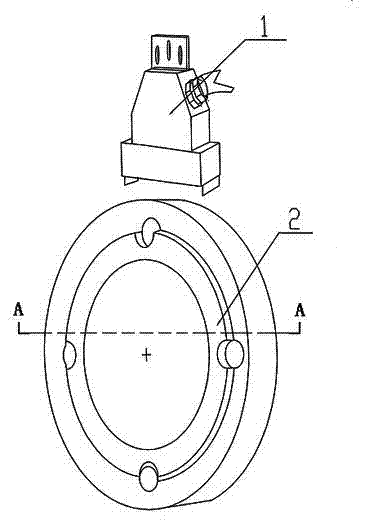
[0019] attached by figure 1 , 2 As shown: the encoder is composed of two parts: the ring encoder body I and the acquisition head II with a gap between the ring encoder body I and the corresponding encoder body I. The encoder body I includes a bearing ring 1. The magnetic ring 2 attached to the upper edge of the bearing body 1, and the protective cover 3 arranged outside the ring bearing ring body 1 and the magnetic ring 2 to protect the magnetic ring 2.

[0020] attached by image 3 As shown: the magnetic coil 2 is specially magnetized according to different pulse requirements, and its N and S polarities are alternately arranged along the circumferential surface of the magnetic coil 2, and the number is an even number.

[0021] attached by Figure 4 As shown: the collection head II includes an upper cover 4, a lower cover 5 with a brush head 8 on the end face, a circuit board 6 arranged inside the upper cover 4 and the lower cover 5, and a magnetic induction chip 7 arranged...


PUM


Abstract

The invention discloses a sensor, and particularly relates to a non-contact annular magnetoelectric rotary encoder. The encoder comprises an annular encoder main body I, and an acquisition head II which is arranged correspondingly to the annular encoder body I, wherein a clearance is formed between the annular encoder main body I and the acquisition head II, the annular encoder main body I comprises a bearing ring body, a magnetic ring stuck and sleeved on the upper edge part of the bearing body, and a protecting cover arranged outside the bearing ring body and the magnetic ring and playing a role of protecting the magnetic ring; and a magnetic induction chip is arranged in the acquisition head II. The magnetoelectric principle is adopted by the encoder; the defects of easiness in cracking of a code disc, high requirement on precision, complex mechanical structure, complex mounting and adjusting process and the like of the traditional photoelectric encoder are overcome; the generation, the receiving and the processing of a signal are realized by selecting and using a magnetoelectric integrated chip; the complex debugging process of the traditional photoelectric encoder is omitted; the production efficiency and the performance of products are greatly improved; and the non-contact annular magnetoelectric rotary encoder which is small in size, high in reliability, resistant in vibration, high in frequency response, low in cost, high in precision, low in error and long in service life is provided.

Description

technical field [0001] The invention discloses a sensor, specifically a non-contact circular magnetoelectric rotary encoder, which can be widely used in numerical control machine tools, elevator industry, navigation, automation, aviation, motor control and industrial automation, etc. field. Background technique [0002] An encoder is a rotary sensor that converts angular displacement into a series of digital pulses. Its basic structure is composed of a light-emitting device, a code disc, a slit, and a receiving element. When the encoder shaft drives the code disc to rotate, the light emitted by the light-emitting element is cut into intermittent light by the code disc and the slit and received by the receiving element to generate an initial signal. After the signal is processed by the subsequent circuit, it outputs a signal. The accuracy of a rotary encoder depends on mechanical and electrical factors such as disc eccentricity, bearing eccentricity, and inaccuracies in the...

Claims


Application Information

Patent Timeline
Patent Type & Authority Applications(China)
IPC IPC(8): G01D5/244
Inventor 倪国东
Owner CHANGCHUN RONGDE OPTICS
Learn More