
Composite ground heating floor

A floor and floor heating technology, applied in the field of building decoration materials, can solve the problems of complex manufacturing process and installation, low heat conduction efficiency, short heat conduction path, etc., and achieve the effect of short heat conduction path, high heat conduction efficiency, and not easy to crack

Inactive Publication Date: 2012-07-04
李渊
View PDF1 Cites 2 Cited by
  • Summary
  • Abstract
  • Description
  • Claims
  • Application Information

AI Technical Summary

Problems solved by technology

[0004] The purpose of the present invention is to provide a composite floor heating floor with short heat conduction path, high heat conduction efficiency, good stability, convenient installation and simple manufacturing process, which solves the problem of long heat conduction path and low heat conduction efficiency in the prior art. Complex manufacturing process and installation

Method used


Image

  • Composite ground heating floor
  • Composite ground heating floor
  • Composite ground heating floor

Examples


Embodiment 1

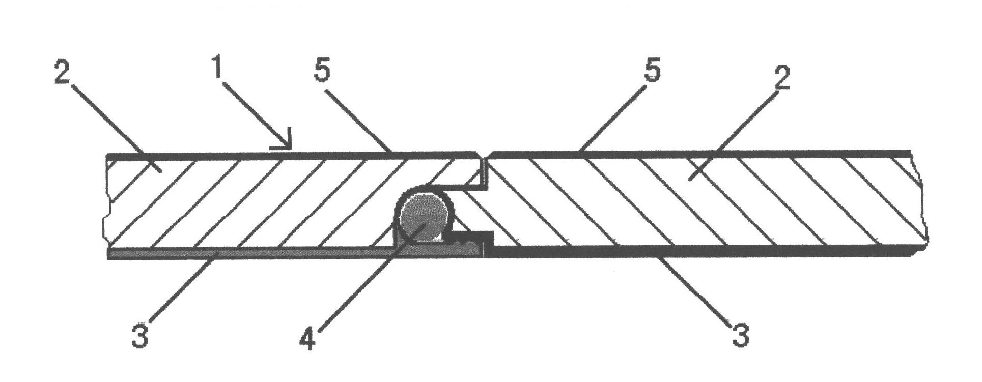
[0025] Embodiment 1: as figure 1 , figure 2 , image 3 , Figure 4 As shown, a composite floor heating floor includes a floor body 1. The floor body 1 includes a base plate 2 and a heat conduction medium layer 3 compounded on the lower surface of the base plate 2. Bonding is achieved; the substrate 2 is a multilayer solid wood composite material and the upper surface of the substrate 2 is provided with a decorative surface 5, and the decorative surface 5 of the present embodiment is a wear-resistant paint layer; one side of the substrate 2 is provided with a first connection structure 21, The other side of the substrate 2 is provided with a second connection structure 22, and the heat conduction medium layer 3 includes a heat conduction portion 30 located on the lower surface of the substrate 2 and a heat conduction portion 30 arranged on both sides of the heat conduction portion 30 and respectively located at the first connection structure 21 and the second connection stru...

Embodiment 2

[0026] Embodiment 2: as figure 1 , Figure 5 and Figure 6As shown, a composite floor heating floor includes a floor body 1. The floor body 1 includes a base plate 2 and a heat conduction medium layer 3 compounded on the lower surface of the base plate 2. To achieve bonding, the bottom surface of the thermally conductive medium layer 3 of this embodiment is pasted with a decorative layer 6, and the decorative layer 6 of this embodiment is an aluminum foil reflective film; the substrate 2 is a multi-layer solid wood composite material and the upper surface of the substrate 2 is provided with a decorative surface layer 5. The decorative surface layer 5 of this embodiment is a wear-resistant paint layer; one side of the substrate 2 is provided with a first connection structure 21, and the other side of the substrate 2 is provided with a second connection structure 22. The heat conducting part 30 on the lower surface and the first heat receiving part 31 and the second heat recei...


PUM


Abstract

The invention relates to a composite ground heating floor and belongs to the technical field of building decoration materials. The composite ground heating floor comprises a floor main body, wherein the floor body comprises a substrate and a heat conducting dielectric layer compounded on the lower surface of the substrate; a connecting groove is formed in one side of the floor body and can be mutually buckled with a connecting tenon arranged on another floor body; the transverse depth of the connecting groove is larger than the transverse length of the connecting tenon; when the connecting groove and the connecting tenon are mutually buckled, a heating piece accommodation cavity for longitudinally extending can be formed in the inner side of the connecting groove; and a heating piece is arranged in the heating piece accommodation cavity and can be used for transmitting heat to the substrate through the dielectric layer during heating until the whole floor body is heated, so that the aim of heating indoor is achieved.

Description

technical field [0001] The invention relates to a composite floor heating floor, which belongs to the technical field of building decoration materials. Background technique [0002] In the prior art, the heat conduction cut-off or heating elements of the geothermal floor are arranged separately from the floor, or are laid on the ground or installed inside other components such as the bottom plate between the ground and the floor, such as a composite geothermal floor (Patent Application No. : CN200510040599.2), it comprises table board, sub-table board, core board, base plate, horizontal heat conduction groove is arranged in core plate, longitudinal heat conduction groove is arranged in base plate, transverse heat conduction groove and longitudinal heat conduction groove are perpendicular to each other and run through, and transverse heat conduction groove The groove and the longitudinal heat conduction groove are filled with heat conduction medium. In the above technical so...

Claims


Application Information

Patent Timeline
IPC IPC(8): E04F15/02
Inventor 李渊
Owner 李渊
Learn More