
In-pipe prestressed steel-pipe truss composite simply-supported beam structure

A steel tube truss and simply supported beam technology is applied in the field of in-pipe prestressed steel tube truss composite simply supported beam structures, which can solve problems such as insufficient mechanical properties, limited spanning capacity of ordinary composite structure simply supported beams, etc. Lightweight structure and easy construction

Active Publication Date: 2012-07-04
CHINA RAILWAY FIFTH SURVEY & DESIGN INST GRP
View PDF6 Cites 17 Cited by
  • Summary
  • Abstract
  • Description
  • Claims
  • Application Information

AI Technical Summary

Problems solved by technology

That is to say, the stress distribution along the bridge span is not evenly distributed, and the mechanical properties of the two materials are not fully exerted. Therefore, under the condition of a certain truss height, the spanning capacity of the simply supported beam of ordinary composite structure is limited to a certain extent.

Method used


Image

  • In-pipe prestressed steel-pipe truss composite simply-supported beam structure
  • In-pipe prestressed steel-pipe truss composite simply-supported beam structure
  • In-pipe prestressed steel-pipe truss composite simply-supported beam structure

Examples


specific Embodiment approach

[0018] The preferred embodiment of the composite simply supported beam structure of the prestressed steel pipe truss in the present invention is as follows:

[0019] It includes a main girder skeleton, on which a bridge deck is arranged, the main girder skeleton is a steel pipe truss structure, and the bridge deck is a concrete structure;

[0020] The main beam skeleton includes a lower chord and an upper chord, the lower chord and the upper chord are connected by multiple web tubes, two adjacent webs form a triangular structure with the upper chord or the lower chord, and the main beam skeleton The cross-sectional shape is an inverted triangle structure;

[0021] The lower chord is an arc-shaped structure that bends downward in the middle, and the side shape of the main beam skeleton is a fish-belly structure;

[0022] Prestressed tendons are arranged in the lower chord.

[0023] An anchoring device is provided at both ends of the lower chord, and the anchoring device inclu...

specific Embodiment

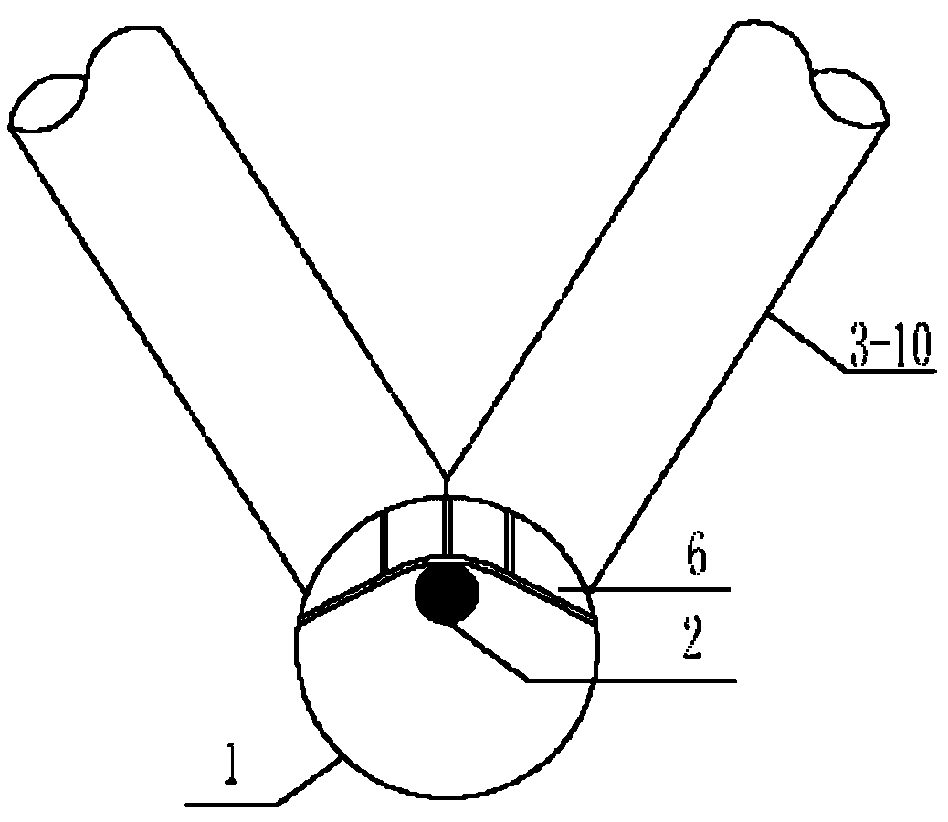
[0034] Such as figure 1 , figure 2 As shown, the main girder skeleton is a fish-belly structure, which can be single or double, and the middle of the two beams is connected into one body through transverse connecting rods 7, 8, and 9.

[0035] Such as figure 1 As shown, specifically, the main beam skeleton can be composed of the lower chord 1, the upper chord 4, and the 3 series of webs (including the webs 3-1 to 3-10). Or the transverse connecting rods form a triangle. The 3 series of abdominal tubes (including 3-1 to 3-10 abdominal tubes) are fixedly connected with the upper chord 4 and the lower chord 1 respectively. The cross-section is an inverted triangle, and the overall skeleton is a fish-belly structure.

[0036] Such as figure 2 As shown, it is a cross-sectional view of a double-width beam structure, and the left half of the bridge axis (double dotted line) is the cross-sectional structure at the support ( figure 1 I-I direction 1 / 2 sectional view), the right...


PUM


Abstract

The invention discloses an in-pipe prestressed steel-pipe truss composite simply-supported beam structure, which comprises a main beam framework and a bridge deck. The main beam framework is in a steel-pipe truss structure, and the bridge desk is in a concrete structure. The main beam framework comprises a lower chord and an upper chord, the upper chord is connected with the lower chord through a plurality of web tubes, each two adjacent web tubes and the upper chord or lower chord form a triangle, and the cross section of the main beam framework is in the shape of an inverted triangle. The lower chord is in an arc structure with the middle arched down, and the lateral side of the main beam framework is in a fish belly structure. A prestressed tendon is arranged in the lower chord. The in-pipe prestressed steel-pipe truss composite simply-supported beam structure is reasonable in stress, light in weight, convenient in construction, and applicable to single-span simply-supported bridges and multi-span simply supported bridges.

Description

technical field [0001] The invention relates to a bridge structure form, in particular to an inner-pipe prestressed steel pipe truss composite simply supported beam structure. Background technique [0002] The combined structure is a combination of two materials with different mechanical properties, and gives full play to their respective mechanical characteristics. For example, concrete has better compressive properties but poor tensile properties, while steel has superior tensile and compressive properties. The structural design can give full play to the compressive performance of concrete and the tensile and compressive performance of steel. For example, the steel-concrete composite structure used for ordinary simply supported beams is the best example. [0003] The composite structure is adopted in the continuous beam, although the structural rigidity is large. However, it is inevitable that a large negative bending moment section will appear at the support position, ...

Claims


Application Information

Patent Timeline
IPC IPC(8): E01D6/00
Inventor 罗九林徐惠纯张立青李闻杨少宏朱勇战郭亚娟梁志新
Owner CHINA RAILWAY FIFTH SURVEY & DESIGN INST GRP
Learn More