
Jar frame for truck

A battery and truck technology, applied in vehicle components, circuits or fluid pipelines, transportation and packaging, etc., can solve problems such as unstable sliding, high material costs, loud noise, etc., and achieve overall function optimization, light structure, and cost reduction. Effect

Inactive Publication Date: 2012-07-04
XIANGYANG SUNRISE MACHINERY
View PDF7 Cites 0 Cited by
  • Summary
  • Abstract
  • Description
  • Claims
  • Application Information

AI Technical Summary

Problems solved by technology

[0003] 1. The battery frame is bulky, which is not conducive to the lightweight requirements of the truck;
[0004] 2. The cost of the battery frame is higher than that of the ordinary single-layer battery frame: the mechanism 15 is heavy, and the heavy double-layer shape makes the material cost higher than that of the ordinary single-layer battery frame;
[0005] 3. The guiding device does not play an obvious guiding role, and the movable bottom plate is easy to shake left and right when it is pulled, and the noise is large;
[0006] 4. After the mechanism 15 is laid flat, there is a transition between the connection with the main body of the battery frame. During the drawing process of the movable bottom plate, when passing through this transition, the sliding is not smooth and there is a lot of noise;
[0007] 5. Twelve bearings are used as the sliding mechanism of the movable floor in the prior art, and the bearings need to be connected to the main body of the battery frame with twelve sets of standard bolts and nuts, which is costly;
[0008] 6. Mechanism 15 is connected to the main body through multiple connecting bolts and nuts, which is inconvenient to install and slide

Method used


Image

  • Jar frame for truck
  • Jar frame for truck
  • Jar frame for truck

Examples


Embodiment Construction

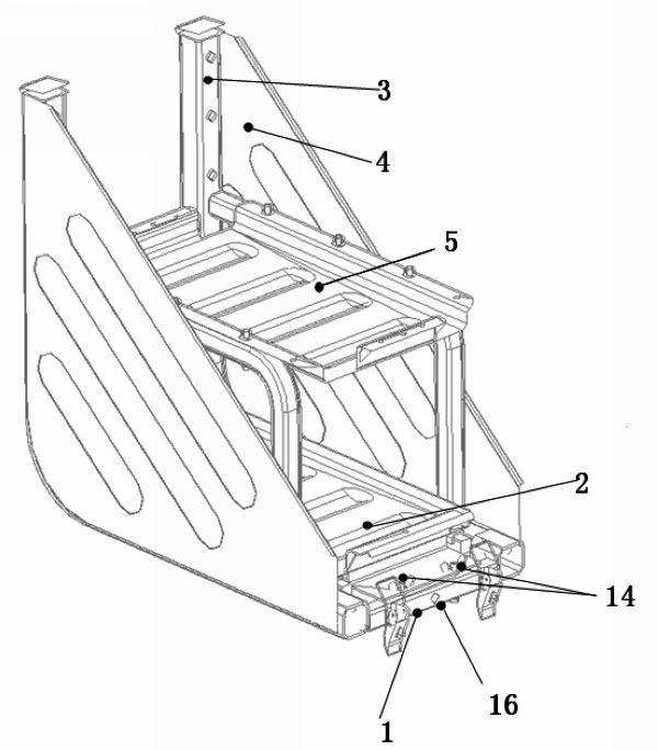
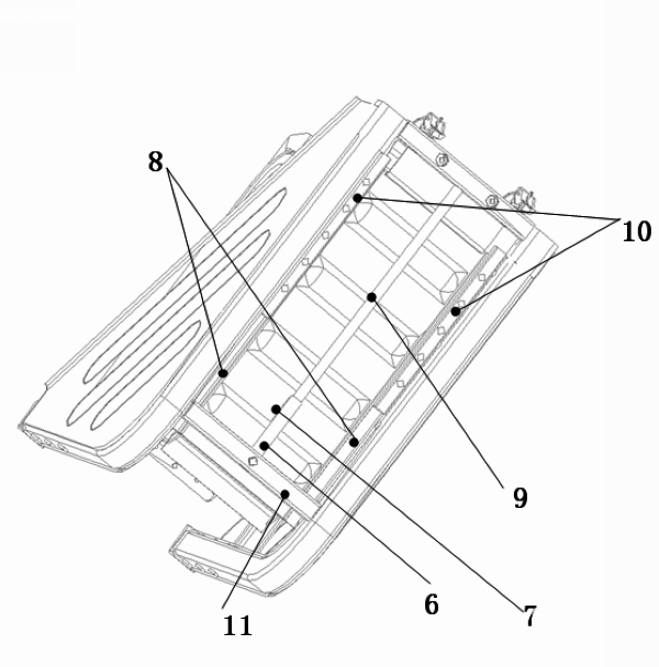
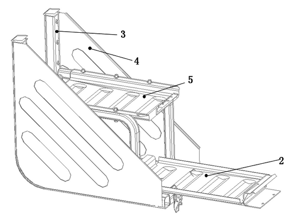
[0020] Such as figure 1 , figure 2 , image 3 , Figure 4 , Figure 5 , Figure 6 As shown, the upper frame 5 is fixed on the main frame 3 with connecting bolts; the side plate is welded on the main frame 3; the ball slideway 10 of the slideway mechanism is welded on the main frame 3, and the ball made of 20*20 square steel Stepped holes are evenly distributed on the type slideway 10, and the balls 12 are installed in the holes through the plugs 13. There is a gap of 0.5 mm between the balls 12 and the bolt plugs 13 to facilitate the rolling of the balls 12. The holes for placing the balls 12 are processed by numerical control. To ensure its smoothness, the movable bottom plate 2 that can slide on the ball-type slideway 10 is in direct contact with the balls 12, and the movable bottom plate 2 is fixed on the front fixing bracket 1 of the battery frame by bolts 14 to prevent the movable bottom plate 2 from sliding back and forth, and the movable The bottom plate 2 can be...


PUM


Abstract

A jar for a truck is used for placing all truck jars. An upper-layer frame is fixed on a main body bracket; a side plate is welded on the main body bracket; a ball-type slideway is fixed on the main body bracket; holes are uniformly distributed in the slideway; balls are mounted in the holes through plugs; a movable baseplate is in contact with the balls directly; the movable baseplate is fixed with a movable baseplate bracket; the movable baseplate is fixed on a front fixed bracket through a bolt I; a guide sleeve is fixed at the bottom of the movable baseplate; a guide rod passes through holes on the front fixed bracket and a rear fixed bracket, which are arranged at two ends of the bottom of the movable baseplate, and the guide sleeve; and the guide rod is fixed on the front fixed bracket and the rear fixed bracket by a bolt II. The integral function is optimized, the weight is reduced by 4.5 kg as compared with an original double-layered jar frame, the size is smaller and the appearance is more attractive, a bearing, a mechanism and a connecting bolt nut in the original scheme are removed, the slideway adopts a ball-type, the sideway and a guiding mechanism are optimized to lower the cost to the great extent, and the guiding mechanism causes the movable baseplate to slide more stably without generating noise.

Description

technical field [0001] The invention relates to the technical field of automobile manufacturing, in particular to a storage battery frame used for storing storage batteries in trucks. Background technique [0002] Such as Figure 7 As shown, although the existing double-deck truck battery frame is compact in structure and beautiful in appearance, it still has the following defects: [0003] 1. The battery frame is bulky, which is not conducive to the lightweight requirements of the truck; [0004] 2. The cost of the battery frame is higher than that of the ordinary single-layer battery frame: the mechanism 15 is heavy, and the heavy double-layer shape makes the material cost higher than that of the ordinary single-layer battery frame; [0005] 3. The guiding device does not play an obvious guiding role, and the movable bottom plate is easy to shake left and right when it is pulled, and the noise is large; [0006] 4. After the mechanism 15 is laid flat, there is a transiti...

Claims


Application Information

Patent Timeline
Patent Type & Authority Applications(China)
IPC IPC(8): B60R16/04
Inventor 程海燕谢智文谢保全
Owner XIANGYANG SUNRISE MACHINERY
Learn More