OTM (oxygen transport membrane)-integrated SOFC (solid oxide fuel cell)/AT (air turbine)/ST (steam turbine) composite power system with zero CO2 (carbon dioxide) emission

A compound power and zero-emission technology, applied in the direction of machines/engines, fuel cell additives, mechanical equipment, etc., can solve the problems of high and low energy consumption, achieve low energy consumption, reduce power consumption, and reduce useful work Effects of loss and power consumption

Inactive Publication Date: 2012-06-27
NORTH CHINA ELECTRIC POWER UNIV (BAODING)
View PDF2 Cites 5 Cited by
  • Summary
  • Abstract
  • Description
  • Claims
  • Application Information

AI Technical Summary

Problems solved by technology

[0003] The present invention mainly does not recover CO 2 Based on the advanced SOFC / ST hybrid power system, integrated oxygen ion transport membrane (OTM), high temperature air turbine and CO 2 Recovery of liquefaction unit composition CO 2 Zero emission system, solving traditional CO 2 capture system due to N 2 Blending results in separation and recovery of CO 2 The problem of high energy consumption greatly reduces the separation and compression of liquefied CO 2 Process energy consumption, keeping total energy consumption low

Method used


Image

  • OTM (oxygen transport membrane)-integrated SOFC (solid oxide fuel cell)/AT (air turbine)/ST (steam turbine) composite power system with zero CO2 (carbon dioxide) emission
  • OTM (oxygen transport membrane)-integrated SOFC (solid oxide fuel cell)/AT (air turbine)/ST (steam turbine) composite power system with zero CO2 (carbon dioxide) emission
  • OTM (oxygen transport membrane)-integrated SOFC (solid oxide fuel cell)/AT (air turbine)/ST (steam turbine) composite power system with zero CO2 (carbon dioxide) emission

Examples


Embodiment Construction

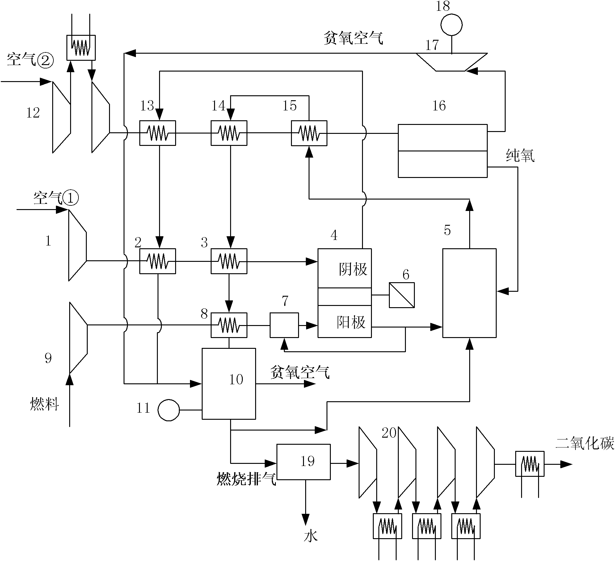
[0023] The present invention provides a CO with integrated OTM 2 The zero-emission SOFC / AT / ST composite power system, the present invention will be further described below through the description of the drawings and specific embodiments, wherein, AT is the abbreviation of air turbine, and ST is the abbreviation of steam turbine.

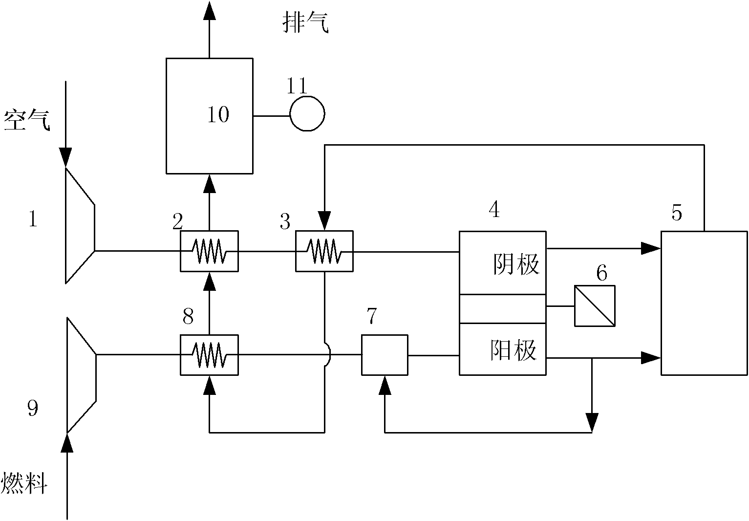
[0024] The benchmark system is a normal pressure system, and the compressor pressurizes the air and fuel only to overcome the pressure loss in the flow process. Its structure diagram is as follows: figure 1 Shown: After the air is compressed by the air compressor 1, it flows through the first heat exchanger 2 and the second heat exchanger 3 in turn, and enters the cathode of the SOFC cell stack 4, and the fuel is compressed by the fuel compressor 9 and passes through the third heat exchanger 8 After heat exchange, it enters the pre-reformer 7 and mixes and reforms with the recycled part of the anode exhaust gas, and then enters the anode of the SOFC ...


PUM


Abstract

An OTM (oxygen transport membrane)-integrated SOFC (solid oxide fuel cell) / AT (air turbine) / ST (steam turbine) composite power system with zero CO2 (carbon dioxide) emission belongs to the technical field of solid oxide fuel cell composite power systems with zero CO2 emission. The composite power system integrates oxygen transport membranes to produce oxygen required by an afterburner, the produced oxygen and a zincode are fed into the afterburner for complete combustion by means of exhaust to only obtain the products including CO2 and H2O, part of combustion tail gas is re-injected into the afterburner via a heat exchanger and by means of waste heat recovery of a waste-heat boiler so that the outlet temperature of the afterburner is kept within the proper range, other part of the combustion tail gas is condensed and separated out through a CO2 recovery unit, and further CO2 is converted into liquid by means of cold compression of a four-interstage cold compressor. The efficient, energy-saving and environment-friendly CO2 composite power system with zero CO2 emission is obtained by integrating an SOFC cell stack system, an OTM system, an AT, the waste-heat boiler, a steam turbine system and a CO2 recovery and liquefying system. By the aid of the system, the total CO2 compression power consumption is low, electric energy is saved, high efficiency is achieved, high-temperature exhaust waste heat of the SOFC is sufficiently used, and energy consumption for separating and capturing CO2 is reduced while efficiency is improved.

Description

technical field [0001] The invention belongs to CO 2 Zero-emission Solid Oxide Fuel Cell (SOFC) composite power system technical field, in particular to an integrated OTM CO 2 Zero-emission SOFC / AT / ST hybrid power system. Background technique [0002] Efficient and environmentally friendly energy systems are the main development trend of future energy utilization systems. There are two major problems in traditional thermal power technology: low efficiency and large amount of polluting gas emissions. The solid oxide fuel cell uses an electrochemical process to generate electricity, breaking through the limitation of Carnot efficiency, and is an efficient power generation system. And due to its unique structural features, the fuel and air are separated by the solid oxide electrolyte, avoiding the N 2 to CO 2 The blending of, thus, capture CO for low energy consumption 2 The capture provides convenient conditions, and it is easy to form efficient CO 2 Zero-emission hybri...

Claims


Application Information

Patent Timeline
IPC IPC(8): F01D15/10H01M8/04
CPCY02E60/50
Inventor 段立强黄科薪杨勇平
Owner NORTH CHINA ELECTRIC POWER UNIV (BAODING)
Why Eureka
Try Eureka