
Vehicle-mounted power generating system for electric vehicle

A technology for electric vehicles and electric motors, applied in electric vehicles, battery circuit devices, current collectors, etc., to achieve the effects of reducing space size and weight, rationally arranging, and improving continuation capability

Active Publication Date: 2014-03-26
CHINA HANGFA SOUTH IND CO LTD
View PDF3 Cites 0 Cited by
  • Summary
  • Abstract
  • Description
  • Claims
  • Application Information

AI Technical Summary

Problems solved by technology

[0003] The purpose of the present invention is to provide a vehicle-mounted power generation system for electric vehicles to solve the technical problems that existing electric vehicles need to install two power drive systems at the same time and need to be quickly charged or replaced in the middle

Method used


Image

  • Vehicle-mounted power generating system for electric vehicle
  • Vehicle-mounted power generating system for electric vehicle

Examples


Embodiment Construction

[0022] The embodiments of the present invention will be described in detail below with reference to the accompanying drawings, but the present invention can be implemented in many different ways defined and covered by the claims.

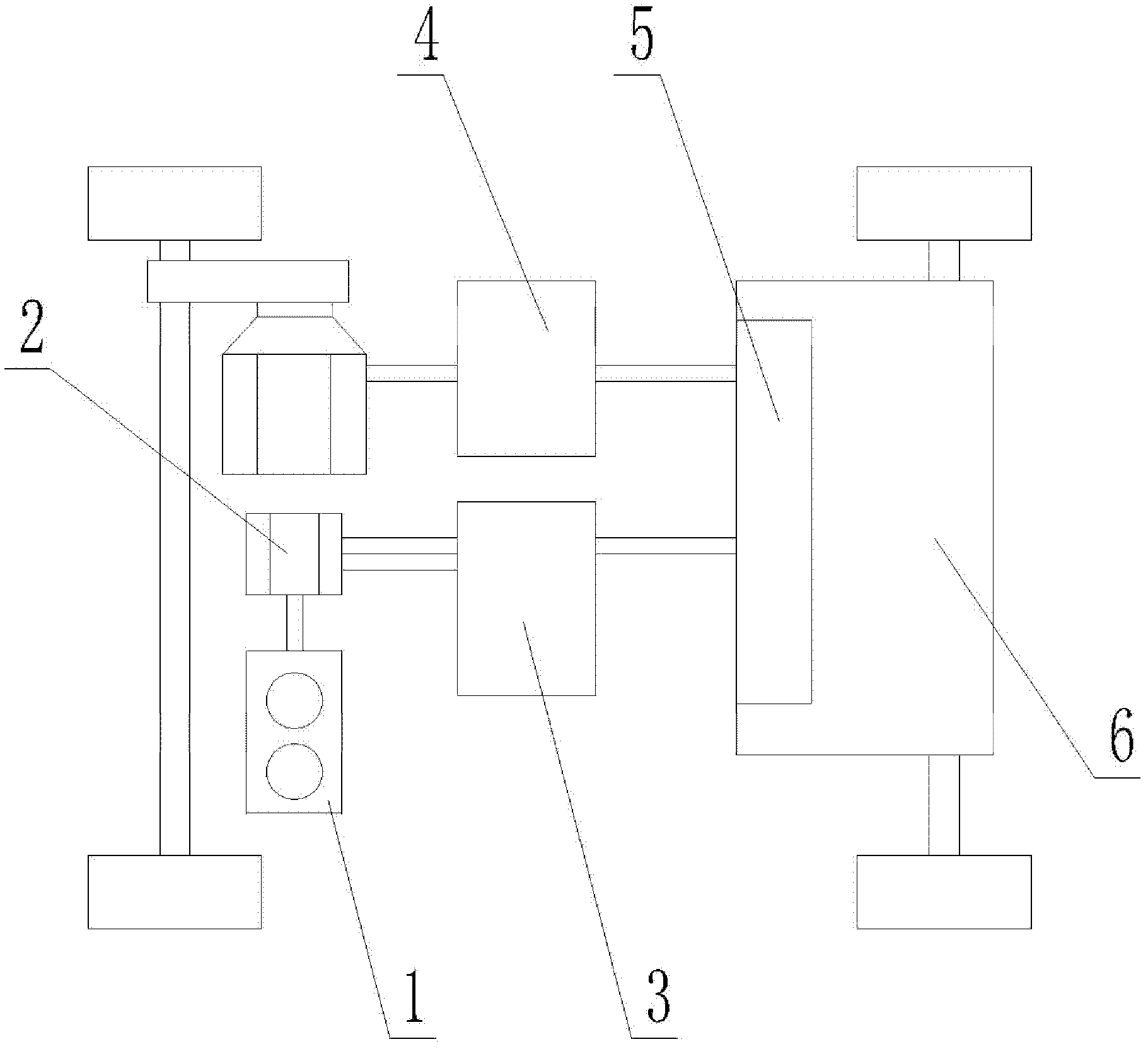
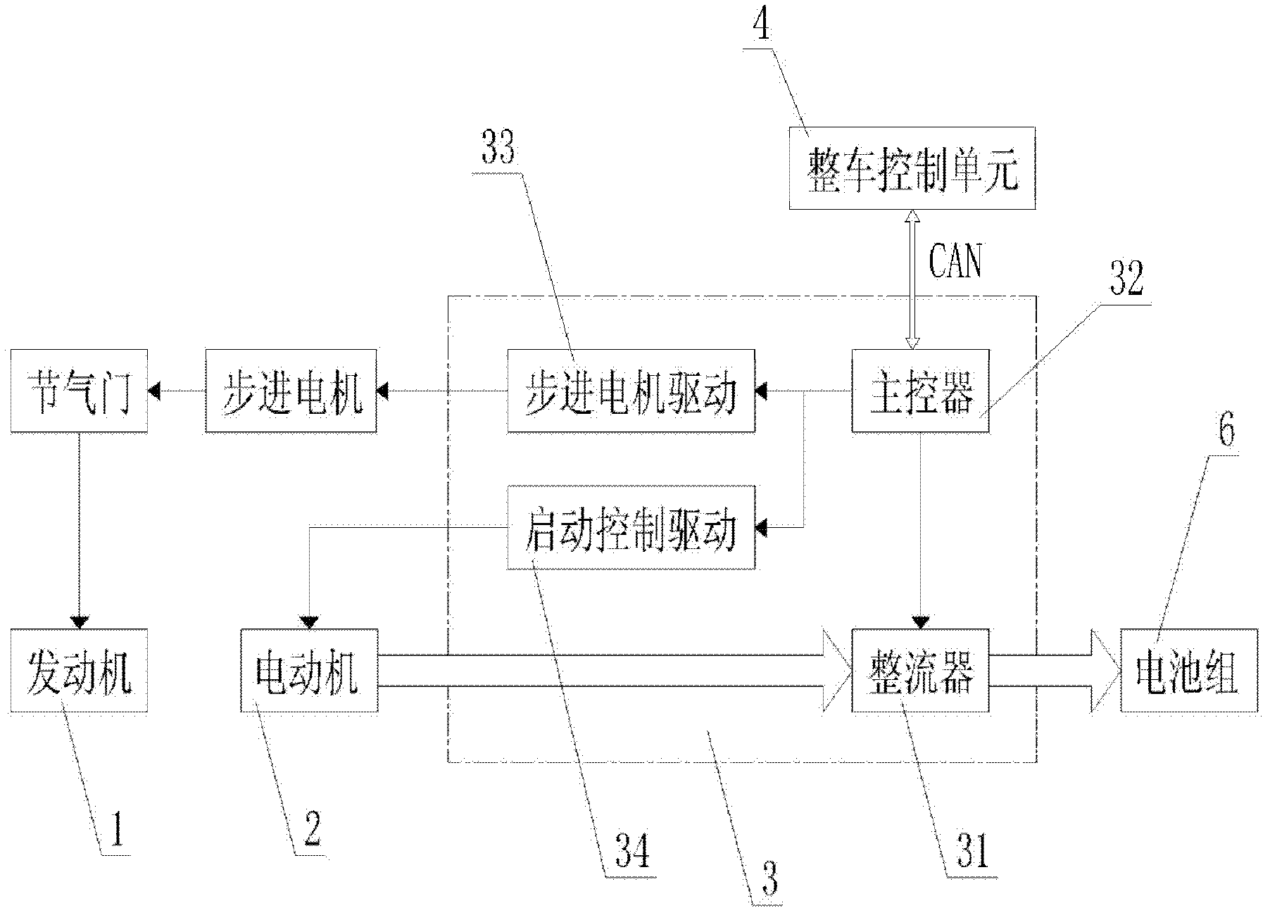
[0023] see figure 1 , The electric vehicle on-board power generation system of the present invention includes: an engine 1 , an electric motor 2 , a rectification control unit 3 , a vehicle control unit 4 , a battery management unit 5 and a battery pack 6 . The engine 1 and the motor 2 are coaxially and rigidly connected into one body. The motor 2 is the power drive unit of the electric vehicle, which converts electric energy into kinetic energy to drive the vehicle; the engine 1 is responsible for burning gasoline or diesel to generate electricity when the vehicle battery is low. , output electric power to charge the battery. Preferably, the engine 1 and the electric motor 2 can adopt an inspiring integrated motor, and the inspiring integrated mot...


PUM


Abstract

The invention provides a vehicle-mounted power generating system for an electric vehicle. The power generating system comprises an engine (1), a motor (2), a rectification control unit (3) and a battery pack (6), wherein the engine (1) and the motor (2) are integrally and rigidly connected together; and the engine (1) is electrically connected with the battery pack (6) through the rectification control unit (3) and used for charging the battery pack (6). In the invention, the electric vehicle is equipped with the engine in coaxially rigid connection with the motor, and the engine is an internal combustion engines which can charge batteries when power of the batteries is low, so that the journey continuing capability of a conventional electric vehicle is greatly improved.

Description

technical field [0001] The invention relates to the field of electric vehicles, in particular to an on-board power generation system of the electric vehicle. Background technique [0002] As a major category of new energy vehicles advocated by the country, electric vehicles have the characteristics of new technologies and new structures. However, the current technical bottleneck lies in power storage technology, and the driving range cannot meet the requirements of mass consumption. The implementation schemes of the prior art include: 1. a dual-drive hybrid electric scheme; 2. a scheme for fast charging or battery replacement. However, there are obvious defects in both schemes: among them, the dual-drive hybrid electric scheme is to add a set of motor drive on the basis of the mechanical drive of the original piston engine power, which requires a larger car body size to meet the needs of the piston engine, machinery and The arrangement of the motor drive assembly, battery p...

Claims


Application Information

Patent Timeline
Patent Type & Authority Patents(China)
IPC IPC(8): H02J7/14
CPCY02T10/7005Y02T10/70
Inventor 刘飞亭施龙吴剑曹立庭王国林
Owner CHINA HANGFA SOUTH IND CO LTD
Learn More