
Ultra wide band radar life detection system and method

A life detection, radar-type technology, applied in the field of life search and rescue detection equipment, can solve the problems of impenetrable metal medium, unfavorable real-time positioning, difficult distance measurement and positioning, etc., to improve system detection performance, simple structure, and reduce system cost Effect

Inactive Publication Date: 2012-06-20
WUXI JUNSHUAI ELECTRONICS TECH
View PDF3 Cites 19 Cited by
  • Summary
  • Abstract
  • Description
  • Claims
  • Application Information

AI Technical Summary

Problems solved by technology

Although the passive detection system using the human body's electrostatic field and ultra-low frequency electromagnetic energy has low power consumption and is not easy to be found, it takes a long detection time to detect signals as low as 3 Hz such as breathing and heartbeat, and it is difficult to measure distance and locate; active The detection system can generally achieve ranging, and if there are two or more detection units, it can locate and even image the target, but the power consumption is high and it is easy to expose
Carriers of through-wall detection technology also have their own characteristics. Electromagnetic wave propagation speed is fast, the working frequency band is high, and it can work at a high repetition frequency, but it cannot penetrate metal media; ultrasonic waves can penetrate metal media, but the propagation speed is slow. It is not conducive to real-time positioning; X-ray penetration and resolution are good, but it is harmful to the human body

Method used


Image

  • Ultra wide band radar life detection system and method
  • Ultra wide band radar life detection system and method
  • Ultra wide band radar life detection system and method

Examples


Embodiment Construction

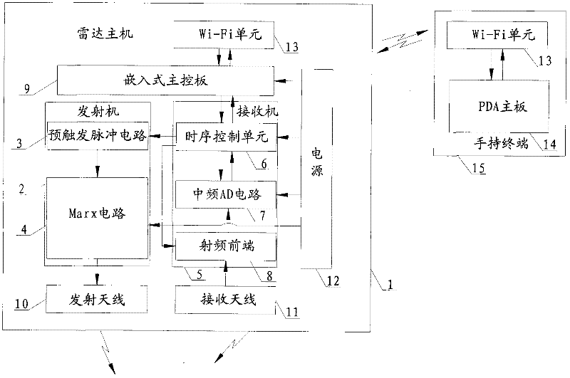
[0031] The present invention will be further described below in conjunction with drawings and embodiments. Please refer to figure 1 as shown, figure 1 It is a structural schematic diagram of the ultra-wideband radar type life detection system of the present invention.

[0032] In this embodiment, an ultra-wideband radar type life detection system includes a radar host 1 and a handheld terminal 15, and the radar host 1 includes a transmitting antenna 10, a receiving antenna 11, a transmitter 2, a receiver 5, an embedded main control Board 9, power supply 12 and Wi-Fi unit 13, the transmitter 2 includes a pre-trigger pulse circuit 3 and a Marx circuit 4, the receiver 5 includes a radio frequency front end 8, an intermediate frequency AD circuit 7 and a timing control unit 6, the Power supply 12 supplies power for Marx circuit 4, embedded main control board 9, intermediate frequency AD circuit 7 and timing control unit 6, and described handheld terminal 15 includes Wi-Fi unit 1...


PUM


Abstract

The invention discloses an ultra wide band radar life detection system and an ultra wide band radar life detection method. The ultra wide band radar life detection system comprises a radar host and a control terminal. The radar host comprises a transmitting antenna, a receiving antenna, a transmitter, a receiver, a main control unit and a communication unit. The control terminal transmits a detection command; the detection command enters the main control system through the communication unit; the main control system triggers the transmitter to generate an ultra wide band narrow pulse; then the ultra wide band narrow pulse is radiated to an observation region by the transmitting antenna; the receiving antenna receives a pulse echo; the pulse echo is transmitted into the receiver to be sampled; data obtained after sampling is transmitted into the main control system to be subjected to clutter rejection, detection and judgment; and the communication unit transmits a processing result of the main control system into the control terminal to display the processing result. Compared with a conventional life detector, the ultra wide band radar life detection system has the advantages that the control terminal can remotely control the radar host to work according to the required mode; and the ultra wide band radar life detection system not only has strong penetrating power, but also has high reliability and high detection accuracy.

Description

technical field [0001] The invention relates to the field of life search and rescue detection equipment, in particular to an ultra-wideband radar life detection system and method. Background technique [0002] As we all know, at the scene of earthquake, fire, building collapse and other accidents, the rapid and accurate detection and positioning of living bodies is the fundamental guarantee for timely and effective rescue of survivors. Through-wall life detection technology can detect targets blocked by various obstacles, especially living objects and their various characteristics, and can be widely used in disaster rescue, anti-terrorism, public security, fire protection, medical and military reconnaissance and other fields. There are many kinds of detection technologies, which can be divided into active and passive according to the working mode, and can be divided into ultrasonic waves, ultra-low frequency electromagnetic waves, microwaves, millimeter waves, X-rays, etc. a...

Claims


Application Information

Patent Timeline
IPC IPC(8): G01V3/12
Inventor 倪晓军倪帅朱国富辛勤
Owner WUXI JUNSHUAI ELECTRONICS TECH
Learn More