
Composite pulsation spot welding process and system

A compound pulse and pulse technology, which is applied in the direction of welding power supply, manufacturing tools, welding equipment, etc., can solve the problems of AC welding machine current peak rise, stability is difficult to guarantee, and high current density peak value has not been tried for capacitor energy storage discharge. To achieve the effect of short discharge time

Inactive Publication Date: 2012-06-20
SHANGHAI JIAO TONG UNIV
View PDF11 Cites 30 Cited by
  • Summary
  • Abstract
  • Description
  • Claims
  • Application Information

AI Technical Summary

Problems solved by technology

[0008] However, the tempering pulse of resistance spot welding is still limited to the power frequency cycle pulse, and there is no attempt to use the high current density peak value and short discharge time current pulse generated by the capacitor energy storage discharge as the tempering pulse
And from the hardware point of view, the current peak current of the AC welding machine needs to be greatly increased in the existing technology, which requires the entire AC pulse welding system to be upgraded, which is costly and difficult to guarantee stability.
However, the research on the discharge pulse treatment of melt capacitor energy storage is still limited to the field of casting, and their method of heating the metal to melting in the casting experiment is not the resistance heating in the resistance spot welding.
There is no research on the operability of capacitor energy storage discharge pulse tempering in resistance spot welding

Method used


Image

  • Composite pulsation spot welding process and system
  • Composite pulsation spot welding process and system
  • Composite pulsation spot welding process and system

Examples


Embodiment Construction

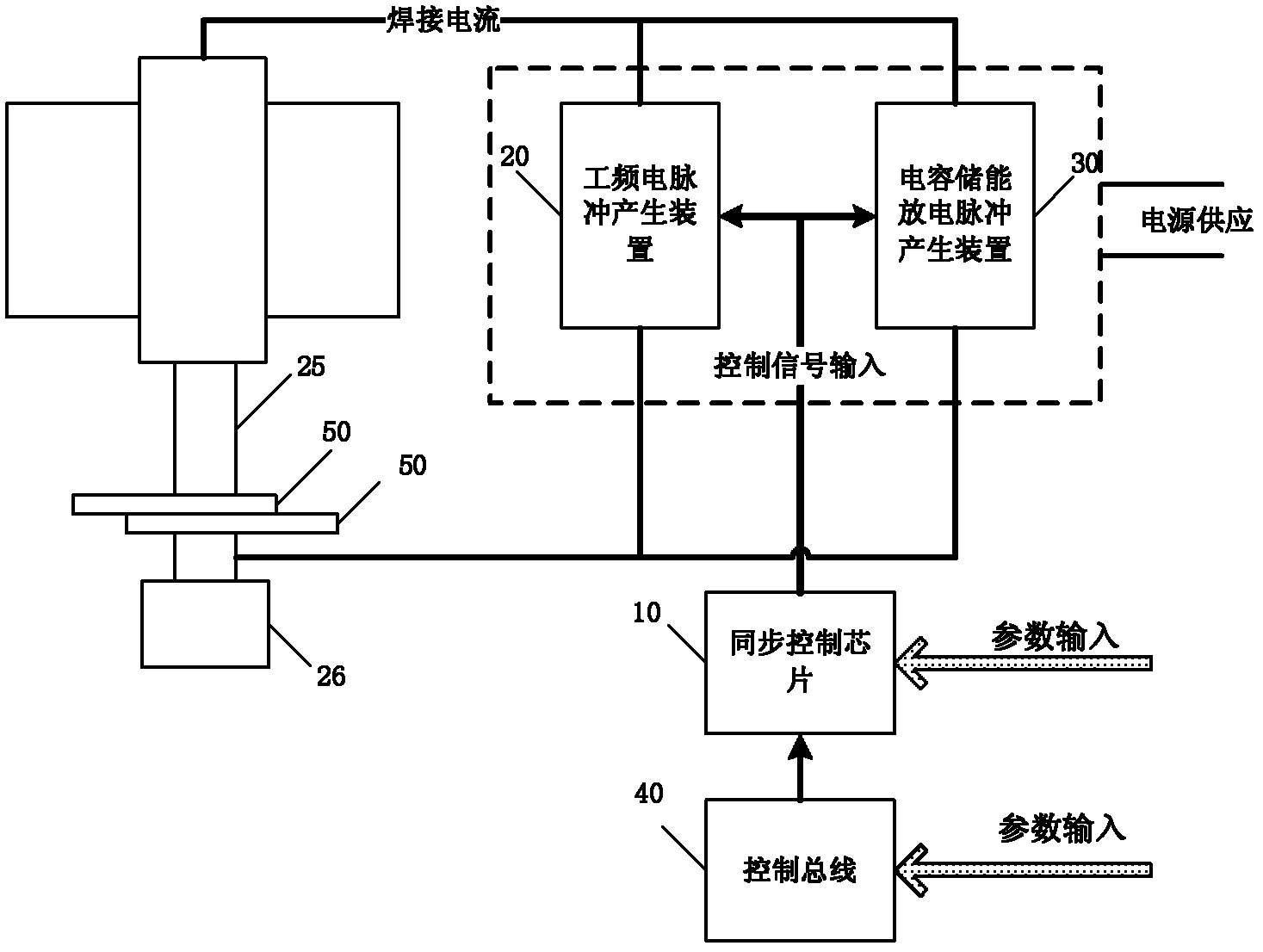
[0029] like figure 1As shown, a preferred embodiment of the composite pulse spot welding system includes: synchronization and control chip 10, power frequency pulse generator 20, capacitor energy storage discharge pulse generator 30 and control bus 40, wherein: synchronization and control chip 10 passes through The control signal output line is connected with the power frequency pulse generating device 20 and the capacitor energy storage discharge pulse generating device 30, and the current in the welding circuit is measured by the sensor. Two output terminals of the power frequency electric pulse generator 20 and the capacitor energy storage discharge pulse generator 30 are connected in parallel, and are jointly connected to the electrode two ends 25, 26, and the power frequency pulse generator 20 and the capacitor energy storage discharge pulse generator 30 are The control signal comes from the synchronization and control chip 10 . In this embodiment, the welding material 5...


PUM


Abstract

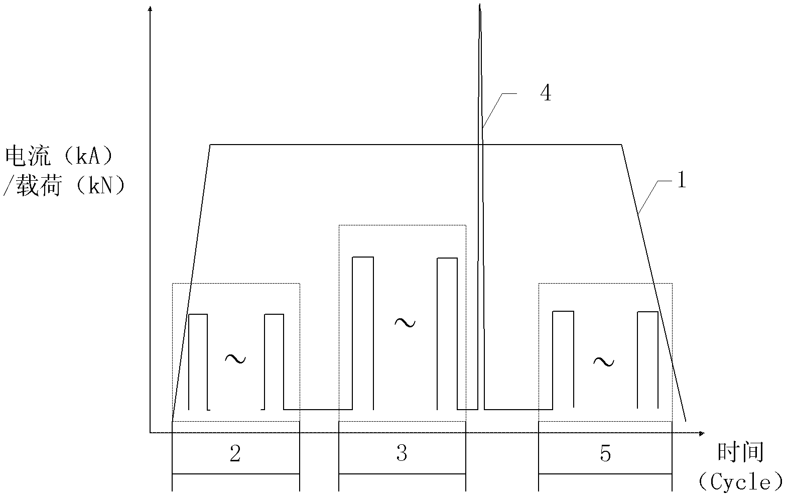
The invention discloses resistance spot welding process and a system, and relates to composite pulsation spot welding process and a system. By the aid of the composite pulsation spot welding process and the system, power-frequency spot welding current of traditional resistance spot welding process and condenser discharge pulses are combined. The condenser discharge pulses with high-current peak values and short discharge time are released in a weld nugget solidification stage after supply of the power-frequency welding current is finished and before supply of power-frequency temper current starts. The composite pulsation spot welding process is realized in the composite pulsation spot welding system, wherein the composite pulsation spot welding system comprises a power-frequency pulse portion, a condenser discharge portion and a synchronous system. By the aid of the composite pulsation spot welding process and the system, welding zone textures can be remarkably improved, crystal grains are refined, anisotropy is weakened, welding cracks are reduced, components are homogenized, and accordingly mechanical performances of resistance spot welding are enhanced.

Description

technical field [0001] The invention relates to a welding process in the field of welding technology, in particular to a compound pulse spot welding process and a welding system thereof. Background technique [0002] The traditional resistance spot welding process has been widely used in industrial production, especially in the field of automobile manufacturing, because of its simple metallurgical process and easy mechanization and automation. However, with the continuous improvement of the welding process and welding quality requirements, how to improve the welding zone structure and welding performance by designing the resistance spot welding current process parameters has become an important task in the research of resistance spot welding technology. [0003] F.Hayat in "The effects of the welding current on heat input, nugget geometry, and the mechanical and fractional properties of resistance spot welding on Mg / Al dissimilar materials" and the effect of welding current...

Claims


Application Information

Patent Timeline
IPC IPC(8): B23K11/11B23K11/24
Inventor 沈耀李奥吕智马佳伟金学军
Owner SHANGHAI JIAO TONG UNIV
Learn More