
Bearing

A bearing, a pair of technology, used in bearings, bearing components, roller bearings and other directions, can solve the problems of small axial load capacity, limited application occasions, power loss, etc., to achieve good axial load capacity, avoid power loss, The effect of reducing drag

Active Publication Date: 2012-06-13
卢雨
View PDF6 Cites 6 Cited by
  • Summary
  • Abstract
  • Description
  • Claims
  • Application Information

AI Technical Summary

Problems solved by technology

[0003] The disadvantage of the existing bearings is that a considerable part of the power will be lost in the resistance generated when the bearing is running. This resistance mainly comes from the friction between the rollers and the cage in the bearing. The greater the resistance, the greater the loss of power
In addition, the axial load capacity of existing bearings is small, which limits its application

Method used


Image

  • Bearing
  • Bearing
  • Bearing

Examples


Embodiment 1

[0026] Example 1: Single row bearing

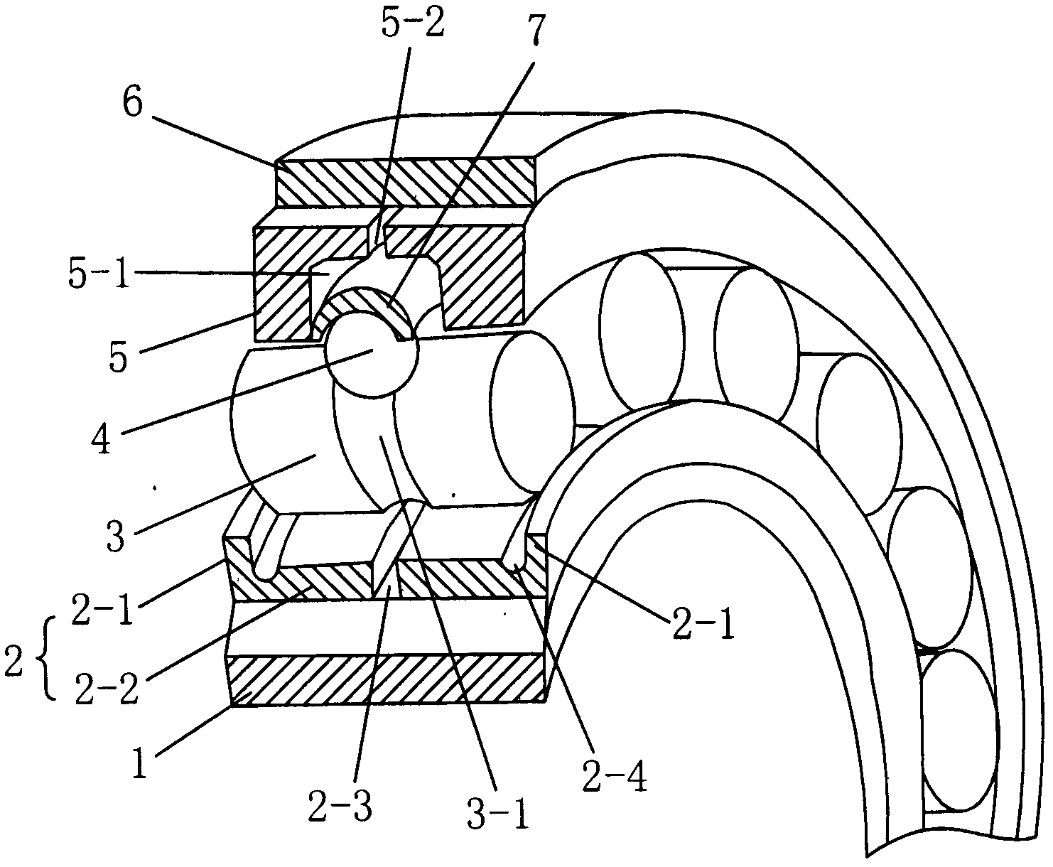
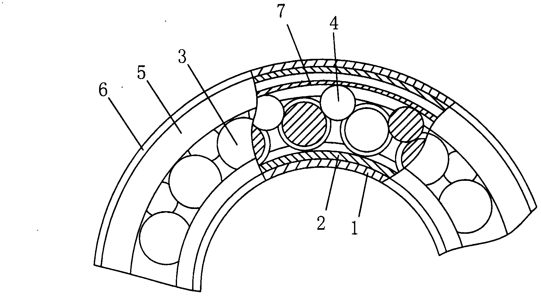
[0027] See Figure 1-2 , the bearing of this embodiment includes: an inner ring 1, a secondary inner ring 2 tightly fitted on the inner ring 1, rollers 3 distributed on the secondary inner ring 2, and a pair of adjacent rollers 3 arranged between The rollers 4, the annular bridge hoops 7 sleeved on each roller 4, the secondary outer ring 5 tightly sleeved on the bridge hoops 7, and the outer ring 6 tightly sleeved on the secondary outer rings 5; The rollers 3 are axially distributed, and each roller 3 is provided with an annular groove 3-1 with a circular arc-shaped cross section, and the rollers 4 are located between the annular grooves 3-1 of adjacent rollers 3; The inner ring of 7 is provided with an arc-shaped groove suitable for movable cooperation with the roller 4; the auxiliary inner ring 2 includes a pair of axially symmetrical distribution on the outer circumference of the inner ring 1, and the outer side of the auxiliary inner...

Embodiment 2

[0033] Example 2: Double column bridge bearing

[0034] On the basis of the above-mentioned embodiment 1, the bearing of this embodiment has the following modifications:

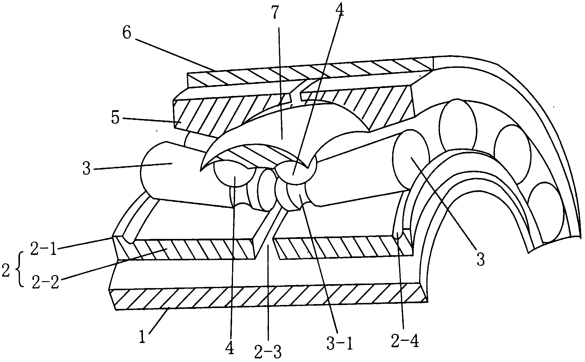
[0035] Such as image 3 , at the same radian position, each of the pair of secondary inner rings 2 is provided with a roller 3, the pair of rollers 3 are axially symmetrically distributed, and the annular groove 3-1 is arranged in the inner ring adjacent to each roller 3 end; the roller 4 is between the annular grooves 3-1 of adjacent rollers 3 distributed on the same circumference; A pair opposite to the annular groove 3-1.

[0036] The roller 3 is in the shape of a truncated cone, and the top end of the roller 3 in the shape of a truncated cone is the inner end; The truncated conical roller is suitable for decomposing the axial force into the radial direction, so it has better axial load capacity, and the roller will not be displaced; More rollers are beneficial to increase the radial load capacity.

...

Embodiment 3

[0042] The assembly method of the bearing described in the above embodiment 1 or 2 includes in sequence:

[0043] The bridge hoop 7 is arranged in the outer ring 6, and then the pair of auxiliary outer rings 5 ​​are symmetrically arranged between the outer ring 6 and the bridge hoop 7;

[0044] The roller 4 and the roller 3 are sequentially arranged on the inner ring of the hoop 7;

[0045]The pair of auxiliary inner rings 2 are arranged symmetrically inside each roller 3;

[0046] The inner ring 1 is tightly fitted on the inner rings of the pair of secondary inner rings 2 .


PUM


Abstract

The invention relates to a bearing which has a simple structure and small resistance and is suitable for axial and radial load. The bearing comprises inner rings, auxiliary inner rings closely sleeved on the inner rings, pin rollers distributed on the auxiliary inner rings, rollers arranged between each pair of adjacent pin rollers, annular bridge hoops which are sleeved rollers, auxiliary outer rings closely sleeved on the bridge hoops, and outer rings closely sleeved on the auxiliary outer rings, wherein the pin rollers are distributed in an axial direction; an annular groove with an arc shaped section is formed on each pin roller, and each roller is positioned between the annular grooves of adjacent pin rollers; the inner rings of the bridge hoops are provided with arc shaped grooves which are in movable fit with the rollers; a pair of auxiliary inner rings are symmetrically distributed on the periphery of the inner rings in the axial direction, flangings which extend outwards in a radial direction are formed on the rims of outer edges of the auxiliary inner rings, and outer end faces of the pin rollers are positioned on the inner sides of the flangings; and a pair of the auxiliary outer rings are symmetrically distributed on the inner circumference of the outer rings in the axial direction, and the inner rings of the auxiliary outer rings form a large annular groove for fixing the bridge hoops.

Description

technical field [0001] The invention relates to a bearing, in particular to a bearing with less resistance and suitable for axial and radial loads. Background technique [0002] A bearing is a component used to determine the relative movement position of a rotating shaft and other parts, and to support or guide it. It is a component that carries gravity and transmits power. [0003] The disadvantage of existing bearings is that a considerable part of the power will be lost in the resistance generated when the bearing is running. This resistance mainly comes from the friction between the rollers and the cage in the bearing. The greater the resistance, the greater the loss of power. In addition, the existing bearings have relatively small axial load capacity, which limits their applications. Contents of the invention [0004] The technical problem to be solved by the present invention is to provide a bearing with simple structure, low resistance and suitable for axial and ...

Claims


Application Information

Patent Timeline
IPC IPC(8): F16C19/49F16C33/58F16C33/30
CPCF16C33/60F16C33/3713F16C19/40F16C19/26F16C19/386F16C33/363F16C33/366
Inventor 卢雨卢平古
Owner 卢雨
Learn More