Model test device for measuring composite foundation lateral deformation and layered sedimentation

A model test device and layered settlement technology, which is applied in the field of geotechnical engineering, can solve problems such as failure to obtain expected results, waste of manpower and material resources, and difficulty in reflecting the characteristics of stress and deformation, and achieve the effect of simple and reasonable structure, convenient and feasible observation

Inactive Publication Date: 2012-06-13
CENT SOUTH UNIV
View PDF5 Cites 26 Cited by
  • Summary
  • Abstract
  • Description
  • Claims
  • Application Information

AI Technical Summary

Problems solved by technology

However, most of the existing model test studies use rigid boundaries, which limit the development of lateral deformation and are quite different from the boundary conditions on site. The accuracy of the test results will inevitably be greatly affected, and it is difficult to reflect the actual force deformation. characteristic
The layered settlement of soil is an important indicator for studying the settlement characteristics and reinforcement mechanism of composite foundations. The existing model tests mainly use the direct embedding of settlement marks in the test soil to test the internal settlement of the soil. However, when the test soil is soft clay, Due to its high viscosity, the directly buried settlement mark is easily covered by the soil during the test, and the mark is lost, resulting in the inability to continuously track and measure the deformation results, failing to obtain the expected results, resulting in a waste of manpower and material resources

Method used


Image

  • Model test device for measuring composite foundation lateral deformation and layered sedimentation
  • Model test device for measuring composite foundation lateral deformation and layered sedimentation
  • Model test device for measuring composite foundation lateral deformation and layered sedimentation

Examples


Embodiment Construction

[0018] The specific implementation manner of the present invention will be described in detail below in conjunction with the accompanying drawings.

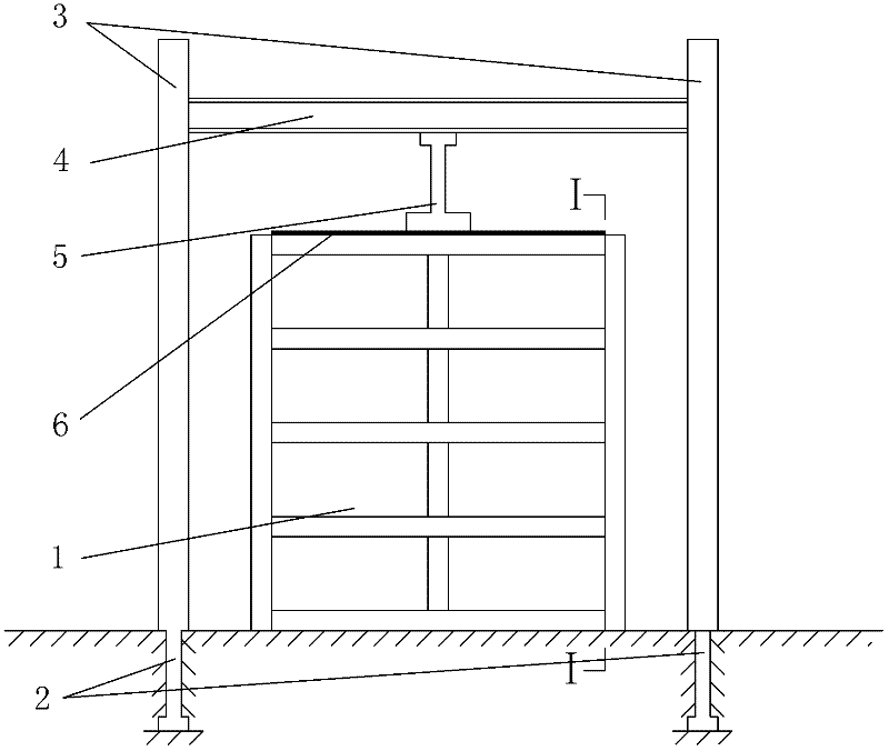
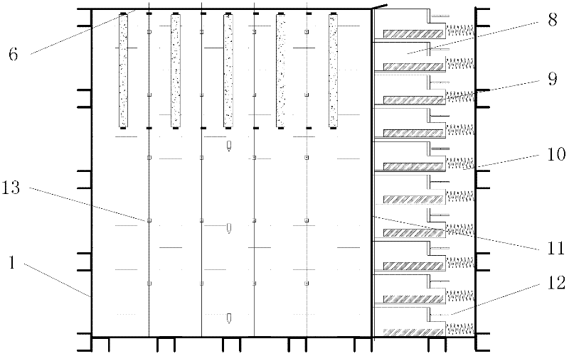
[0019] A model test device capable of measuring lateral deformation and layered settlement of soil, the test device includes a model tank 1, a reaction tank 2, a vertical reaction frame 3, a lateral reaction beam 4, a vertical jack 5, and a load Board 6, frame 7, drawer 8, slide rail 9, spring 10, silicone pad 11, displacement gauge 12 and layered settlement mark 13. The model tank 1 is used to fill the test soil, the vertical reaction frame 3 is fixed in the reaction tank 2, and the horizontal reaction beam 4 is connected between the vertical reaction frames 3 by high-strength bolts , the vertical jack 5 is placed between the transverse reaction beam 4 and the loading plate 6, the loading plate 6 is placed on the test soil, the model tank 1 is a rectangular box, and the bottom of the model tank 1 The left and right sides and th...


PUM


Abstract

The invention relates to a model test device for measuring composite foundation lateral deformation and layered sedimentation. The model test device comprises a counter-force groove, a loading plate, a vertical counter-force frame, a lateral counter-force frame, a vertical jack and a model groove and is characterized in that: the left side, the right side, the rear side and the bottom of the model groove are sealed; the front side of the model groove is sealed by adopting a high-strength organic glass plate; the right side of the model groove is provided with a lateral stress measuring mechanism; and a test soil body is arranged in the model groove. The model test device disclosed by the invention is mainly suitable for a composite foundation indoor model test with remarkable lateral deformation of a soft soil foundation and the like, can be used for simulating single-layer or double-layer and multi-layer foundations, has the advantages of simple and reasonable structure and convenient and feasible conversation, can realize indoor simulation of composite foundation lateral deformation and layered sedimentation under complex conditions and can provide basis for practical engineering composite foundation design optimization and reinforced mechanism analysis.

Description

technical field [0001] The invention belongs to the technical field of geotechnical engineering, in particular to a model test device for measuring lateral deformation and layered settlement of a composite foundation. Background technique [0002] In recent years, my country's high-speed railway and highway construction has developed rapidly. This large-scale new line construction will inevitably encounter soft foundations, and high-speed railways and highways put forward very strict control requirements for subgrade settlement. Stability, post-construction settlement and post-construction uneven settlement, various ground treatment methods have emerged as the times require. Composite foundation has been widely used as an economical and effective foundation treatment method, but its theoretical research on reinforcement mechanism and settlement calculation method lags behind engineering practice. Although the field test can provide more direct and reliable data, which can di...

Claims


Application Information

Patent Timeline
Patent Type & Authority Applications(China)
IPC IPC(8): E02D33/00E02D1/00
Inventor 徐林荣王宏贵刘常虹刘维正左申
Owner CENT SOUTH UNIV
Why Eureka
Try Eureka