
Two-section type single loop mixed refrigerant natural gas liquefaction process and device

A technology for mixing refrigerant and natural gas, which is applied in the field of two-stage single-cycle mixed refrigerant natural gas liquefaction process and equipment, can solve problems such as complex process and complex process, and achieve the effects of simple process process, simple process and low energy consumption.

Inactive Publication Date: 2012-06-13
CHINA UNIV OF PETROLEUM (BEIJING)
View PDF10 Cites 15 Cited by
  • Summary
  • Abstract
  • Description
  • Claims
  • Application Information

AI Technical Summary

Problems solved by technology

At the same time, in the technical solution disclosed in this patent, the refrigerant after the second-stage compression and cooling of the compressor is also a gas-liquid two-phase, and a second gas-liquid separation tank needs to be installed. Liquid two-phase refrigerants are provided with flow channels, and independent J-T valves are used for throttling refrigeration, so there are three refrigerant flow channels and three J-T valves, and the process is relatively complicated.
[0007] Chinese utility model patent 201020218282.X discloses a device for liquefying natural gas using a single mixed working fluid refrigeration, which uses three-stage compression, and the process is more complicated

Method used


Image

  • Two-section type single loop mixed refrigerant natural gas liquefaction process and device
  • Two-section type single loop mixed refrigerant natural gas liquefaction process and device

Examples


Embodiment 1

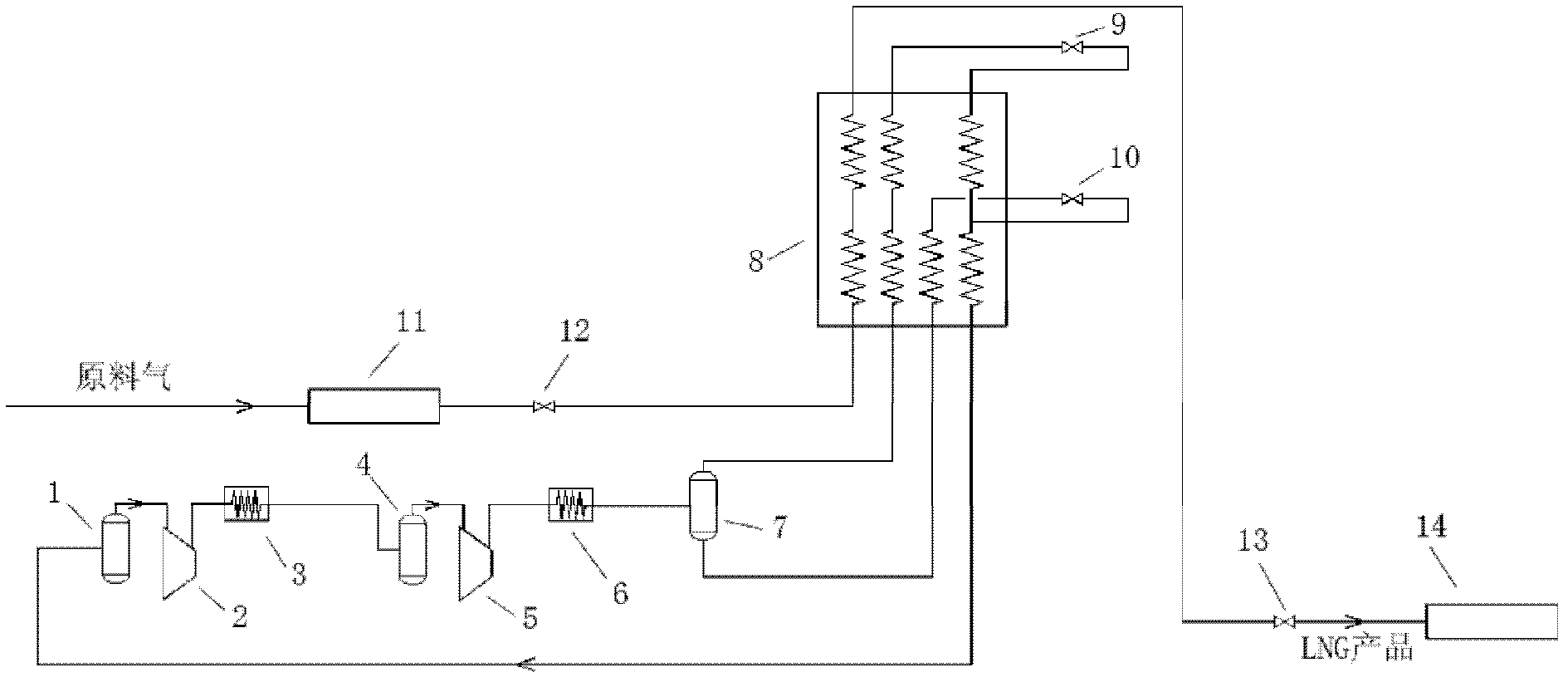
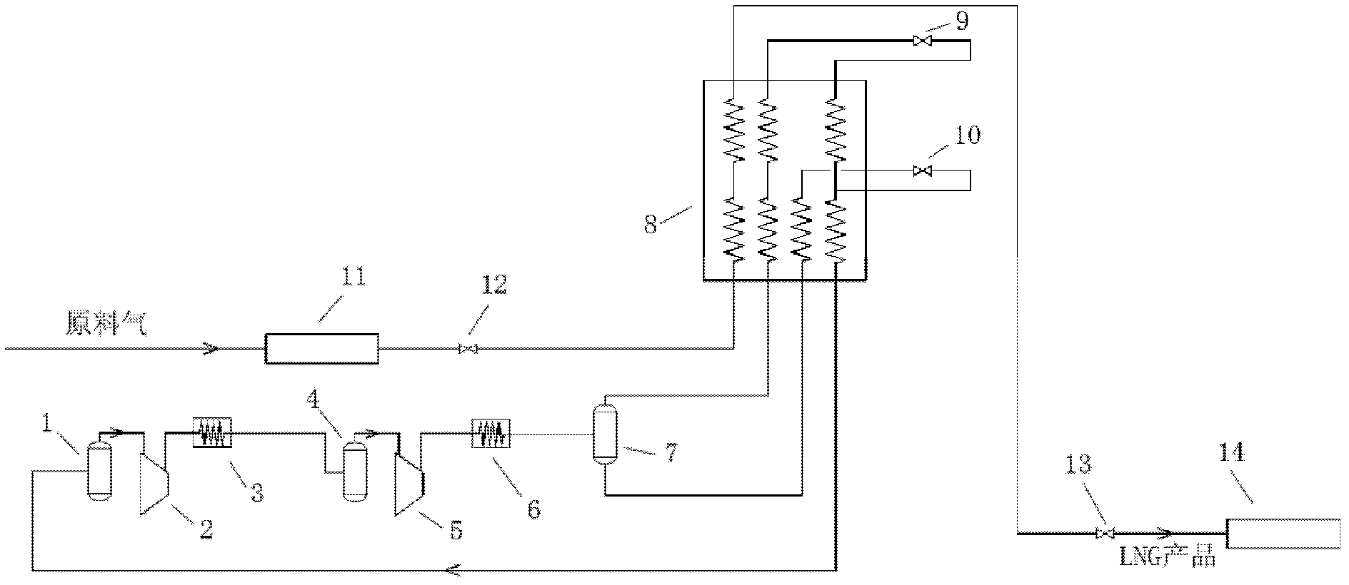
[0058] This embodiment provides a two-stage single-cycle mixed refrigerant natural gas liquefaction equipment, the structure of which is as follows figure 1 As shown, the natural gas liquefaction equipment includes: a first suction tank 1, a first compressor 2, a first cooler 3, a second suction tank 4, a second compressor 5, a second cooler 6, and a gas-liquid separation tank 7 , plate-fin cold box 8, first throttle valve 9, second throttle valve 10, wherein:

[0059] The plate-fin cold box 8 adopts an aluminum brazed plate-fin low-temperature heat exchanger, which is equipped with four flow channels, such as figure 1 As shown, the leftmost is the first flow channel (natural gas pipeline), and then from left to right are the second flow channel, the third flow channel, and the fourth flow channel;

[0060] Both the first compressor 2 and the second compressor 5 use two-stage compression centrifugal hybrid refrigerator compressors;

[0061] The first cooler 3 and the second ...

Embodiment 2

[0074] This embodiment provides a two-stage single-cycle mixed refrigerant natural gas liquefaction process, which is a natural gas liquefaction process using the equipment provided in Embodiment 1, including the following specific steps:

[0075] The mixed refrigerant with a pressure of 350kPa to 450kPa (preferably 420kPa) is compressed by the first compressor 2 to the range of 600kPa to 1000kPa (preferably 847kPa), and then cooled to 25°C to 45°C by the first cooler 3 (with ambient temperature), then inhaled by the second suction tank 4, then compressed into the second compressor 5 to 3500kPa to 4500kPa (preferably 4080kPa), and then cooled to 25°C to 45°C by the second cooler 6 (with ambient temperature related);

[0076] At this time, the mixed refrigerant is a gas-liquid two-phase, and after being input into the gas-liquid separation tank 7 for gas-liquid separation, a gas-phase refrigerant and a liquid-phase refrigerant are obtained, and the two are processed separately:...


PUM


Abstract

The invention relates to a two-section type single loop mixed refrigerant natural gas liquefaction process and a device. The process comprises the following steps: conducting two-section compression cooling on mixed refrigerant, enabling the mixed refrigerant to be in gas state after first section compression cooling, conducting first gas-liquid separation after second section compression cooling, obtaining gas state refrigerant and liquid state refrigerant; enabling the liquid state refrigerant to enter an ice chest for cooling and then throttling, cooling and returning to the ice chest for providing cooling amount of a high temperature position; enabling the gas state refrigerant to enter the ice chest for cooling to a low temperature and then throttling, cooling and returning to the ice chest for providing cooling amount of a low temperature position; enabling the gas state refrigerant to be converged with the liquid state refrigerant returning to the ice chest after throttling to improve the cooling amount of the high temperature position; conducting two-section type compression cooling on the mixed refrigerant providing the cooling amount to enter next circulation; enabling natural gas to enter the ice chest for cooling, and then obtaining liquefied natural gas products after throttling. The invention further provides a liquefied natural gas device used in the process. The process is simple in process, and has the advantages of high liquefaction rate, low energy consumption and the like.

Description

technical field [0001] The invention relates to a natural gas liquefaction process and equipment, in particular to a two-stage single-cycle mixed refrigerant natural gas liquefaction process and equipment. Background technique [0002] Natural gas is a high-quality and clean fossil energy. After liquefied, the volume of natural gas is about 1 / 625 of its original volume, so it is convenient for storage and transportation. Compared with pipeline gas, liquefied natural gas (LNG) plays an irreplaceable role in the development of scattered gas fields and marginal gas fields, the utilization of coalbed methane, the development and utilization of offshore natural gas, and the introduction of overseas natural gas. [0003] Natural gas liquefaction has three types: cascade refrigeration cycle, mixed refrigerant refrigeration cycle and expander refrigeration cycle. Among them, the mixed refrigerant cycle (MRC) process is relatively simple, and has high energy utilization efficiency a...

Claims


Application Information

Patent Timeline
Patent Type & Authority Applications(China)
IPC IPC(8): C10L3/10F25J1/02
Inventor 孙恒马文华
Owner CHINA UNIV OF PETROLEUM (BEIJING)
Learn More