
Heat supplying method of cooling water residual heat recycling energy-saving system of thermal power plant

A waste heat recovery and energy-saving system technology, applied in hot water central heating systems, heating systems, household heating and other directions, can solve the problems of large temperature difference between high temperature water and ground temperature, affecting the efficiency of power generation, low utilization rate, etc., to achieve waste heat Effective, low heat loss, low power consumption

Inactive Publication Date: 2012-06-06
张宏伟
View PDF3 Cites 8 Cited by
  • Summary
  • Abstract
  • Description
  • Claims
  • Application Information

AI Technical Summary

Problems solved by technology

This method has the following disadvantages: first, the heat pump is driven by steam, and steam needs to be taken from the end of the steam turbine, which affects the efficiency of power generation, and the risk is high; The temperature difference between high-temperature water and ground temperature is large, the heat loss in the transportation process is large, and thermal expansion and contraction have high requirements on pipelines and related equipment, which requires large investment and low utilization rate

Method used


Image

  • Heat supplying method of cooling water residual heat recycling energy-saving system of thermal power plant
  • Heat supplying method of cooling water residual heat recycling energy-saving system of thermal power plant
  • Heat supplying method of cooling water residual heat recycling energy-saving system of thermal power plant

Examples


Embodiment 1

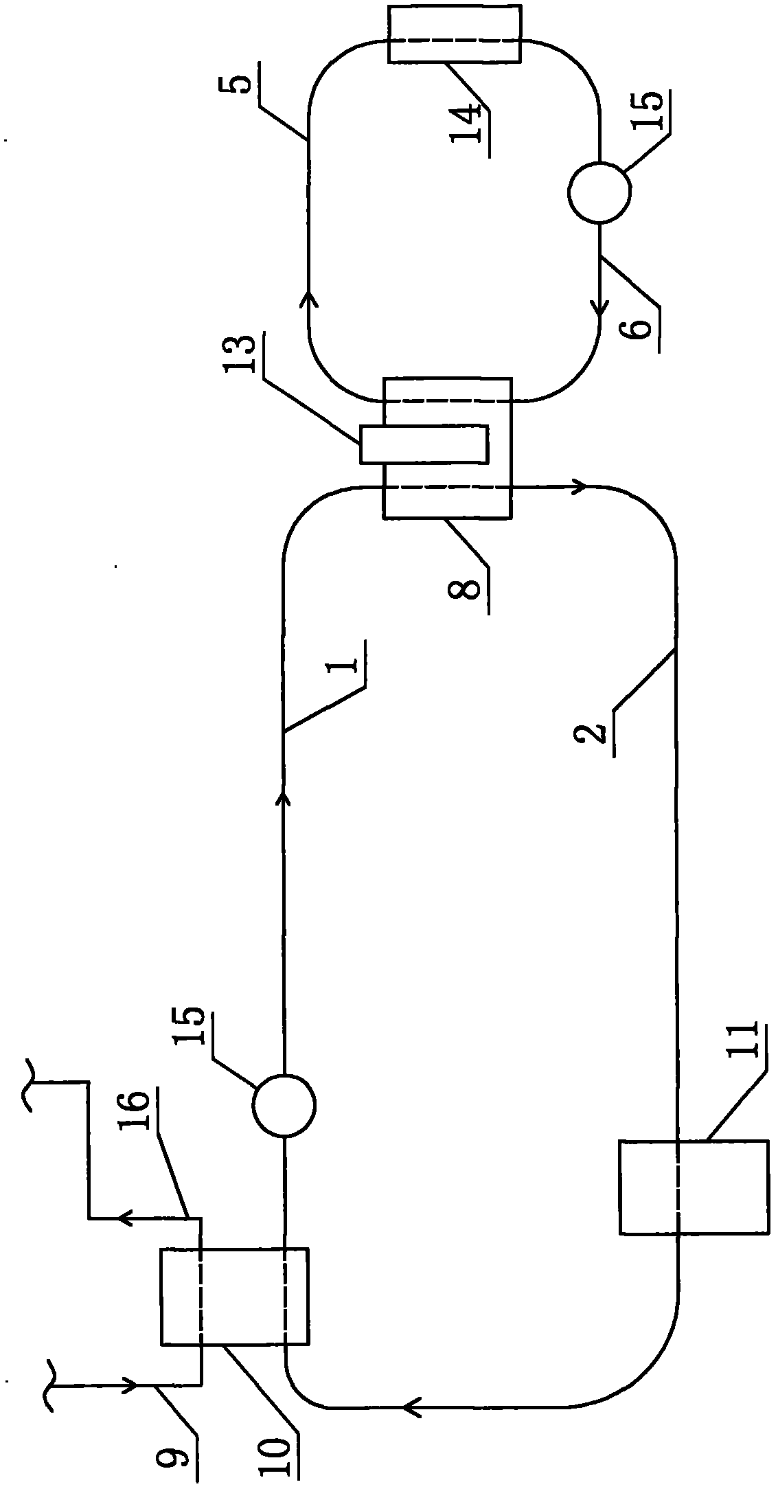
[0024] Embodiment 1: as figure 1 As shown, the heat supply method for realizing the energy saving system of cooling water waste heat recovery in a thermal power plant includes a heat exchange station E8, a condenser 10, a cooling tower 11, a user terminal 14, a water pump 15, piping systems and accessories. A heat exchange station E8 is built in the urban area. An electric-driven heat pump 13 is installed in the heat exchange station E8. Both the condenser 10 and the heat exchange station E8 are equipped with water inlet and outlet ports. The outlet pipe A1 is connected to the water inlet of the heat exchange station E8. The interface and the water outlet interface of the condenser 10, the return water pipe A2 connects the water outlet interface of the cooling tower 11, the heat exchange station E8, and the water inlet interface of the condenser 10, so that the condenser 10 and the heat exchange station in the urban area Between E8 and the cooling tower 11, the pipeline for th...

Embodiment 2

[0027] Embodiment 2: The advantage of Embodiment 1 is that the investment is low, but the cooling water circulation pipeline of the thermal power plant needs to be modified, and if a failure occurs on the way to the urban area, it will affect the cooling system of the thermal power plant. In view of this disadvantage, the second solution is designed as follows:

[0028] Such as figure 2 As shown, the heat supply method for realizing the heat recovery and energy saving system of the cooling water waste heat of the thermal power plant, the difference between the system and the embodiment 1 is that it also includes the heat exchange station D7. A heat exchange station D7 is built in the thermal power plant. A plate heat exchanger 12 is installed in the heat exchange station D7. The heat exchange station D7 is provided with an inlet and outlet water interface. Water interface, return water pipe A2 connects cooling tower 11, heat exchange station D7 and water inlet interface of c...

Embodiment 3

[0032] Embodiment 3: as image 3 As shown, the difference between it and Embodiment 2 is that multiple heat exchange stations E8 equipped with heat pumps 13 are established in parallel in urban areas, that is, heat exchange stations E8 can be established in each heating district or heating unit.


PUM


Abstract

The invention provides a heat supplying method of a cooling water residual heat recycling energy-saving system of a thermal power plant. In the method, steam produced by action of the thermal power plant flows into a condenser through a steam pipeline, and is subjected to heat release and liquefaction; cooling water absorbs heat released when the steam is liquefied in the condenser, and is delivered to a heat exchange station E through a water outlet pipeline A to serve as a low-temperature heat source; water in a heat supply network is heated by utilizing the heat of the low-temperature heat source under the action of a heat pump, and flows into a cooling tower through a return pipeline B; and the water in the heat supply network is heated in the heat exchange station E and delivered to a client end so as to be utilized as a heat supply source, and returns to the heat exchange station E after supplying heat. The temperature of cooling water delivered to the heat exchange station E in urban areas is 35-45 DEG C, so that low-temperature delivery is realized, and the heat loss is small.

Description

technical field [0001] The invention relates to the technical field of waste heat reuse of cooling water in a thermal power plant, in particular to a heat supply method for an energy-saving system for recovering waste heat from cooling water in a thermal power plant. Background technique [0002] At present, thermal power plants in the society generate steam through thermal heating, and the steam drives the steam turbine to rotate and cut the magnetic field lines to generate electricity. However, the efficiency of thermal power generation is only about 40%, and about 60% of the heat energy of the steam passing through the steam turbine is not utilized, and it is directly passed into the condenser to liquefy and lose the heat energy to the environment. In order to save energy, protect the environment, and utilize the above-mentioned wasted energy, there have been many schemes, such as the invention patent "A method for recovering waste heat from thermal power plants and casca...

Claims


Application Information

Patent Timeline
Patent Type & Authority Applications(China)
IPC IPC(8): F24D3/18F24D3/02
Inventor 张宏伟
Owner 张宏伟
Learn More