Optical transceiver and fiber-optic gyro

An optical transceiver and light source technology, applied in the field of navigation systems, can solve the problems of complex and expensive technology

Inactive Publication Date: 2012-05-23
NORSROP GRUMAN LITEF GMBKH
View PDF8 Cites 7 Cited by
  • Summary
  • Abstract
  • Description
  • Claims
  • Application Information

AI Technical Summary

Problems solved by technology

The technology required for this approach is complex and expensive
Additionally, additional optical loss is expected

Method used


Image

  • Optical transceiver and fiber-optic gyro
  • Optical transceiver and fiber-optic gyro
  • Optical transceiver and fiber-optic gyro

Examples


Embodiment Construction

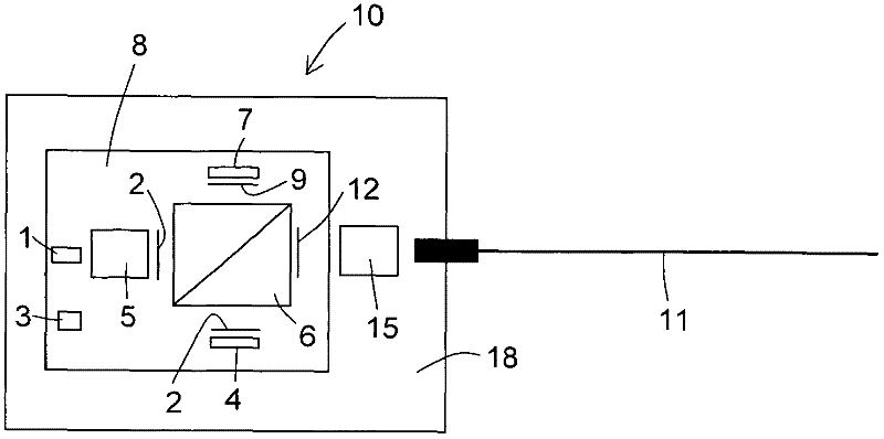
[0015] figure 1 An optical transceiver 10 is shown, wherein the optical and optoelectronic components of the optical transceiver 10 are arranged on a support. According to one embodiment, the optical transceiver 10 comprises a temperature regulation unit with a temperature sensor 3 and a thermoelectric cooling element 8 (TEC, Thermoelectric Cooler). In this embodiment, at least some optical components and optoelectronic components may be configured (integrated) on top of the TEC 8 . The TEC 8 is, for example, a Peltier element and may in turn be fastened to a carrier such as a substrate 18 comprising silicon, silicon dioxide, glass, ceramic or plastic, or comprising multilayer One or more of the above materials. According to another embodiment, the TEC 8 and the substrate 18 are arranged spatially apart from each other and the TEC 8 is thermally conductively connected to the substrate 18 or the light source 1 via a coupling element, i.e. the coupling element thermally couple...


PUM


Abstract

The invention relates to an optical transceiver (10) comprising a substrate (18) having a temperature control device (8, 3), a light source (1), a light conducting fiber (11), a detector (4), a lens (5) for collimation of the light from the light source (1), a coupling lens (15) for focusing the light beam into the light conducting fiber (11) and a beam splitter (6) that deflects one part of the collimated light beam into a wavelength stabilization unit (27) and another part of the collimated light beam into the coupling lens (15). According to the invention, a wavelength stabilization unit (27) registers and compensates for a light wavelength drift in the light source (1). The optical transceiver (10) according to the invention has a super luminescent diode as a light source (1) and can be integrated in a fiber optic gyro (100), for example.

Description

Background technique [0001] Fiber optic gyroscopes are used, for example, in navigation systems. Fiber optic gyroscopes used in inertial navigation systems (INS) requiring high precision are usually based on very stable hyperfluorescent light sources with a wavelength of about 1550 nm. The temperature-dependent wavelength dependence of hyperfluorescent light sources is typically 10 ppm / °C at 1550 nm. Improvements to the above values ​​to only about 0.05 ppm / °C can be achieved by using wavelength stabilizing elements such as thermally compensated Bragg gratings. [0002] Superluminescent diodes (SLDs) are cheap but unstable semiconductor light sources, and their instability has previously prevented SLDs from being used in fiber optic gyroscopes in precision-critical systems. The scale factor (scale factor) accuracy of the SLD is relatively low, which is mainly due to the unstable wavelength of the SLD. For example, on the one hand, the wavelength of SLD is closely related to...

Claims


Application Information

Patent Timeline
Patent Type & Authority Applications(China)
IPC IPC(8): H04B10/155G01C19/72H04B10/572
CPCG01C19/721H04B10/572
Inventor 斯文·沃伊特
Owner NORSROP GRUMAN LITEF GMBKH
Why Eureka
Try Eureka