Compressor

一种压缩机、压缩空间的技术,应用在压缩机领域,能够解决不耐于旋转式压缩机横向振动、很难装配、降低润滑性能等问题,达到提高结构稳定性及装配性、生产及装配容易、减少横向振动的效果

Inactive Publication Date: 2012-05-23
LG ELECTRONICS INC
View PDF13 Cites 6 Cited by
  • Summary
  • Abstract
  • Description
  • Claims
  • Application Information

AI Technical Summary

Problems solved by technology

[0012] However, in the rotary compressor disclosed in the above-mentioned U.S. Patent Laid-Open Publication, although one end of the fixed shaft is fixed to the airtight container, since the other end of the fixed shaft is separated from the airtight container, it is suspended from the airtight container. It is manufactured in the shape of a closed container, so it is difficult to assemble the center of the fixed shaft, and it is very intolerant to the lateral vibration caused by the inevitable eccentric rotation in the properties of the rotary compressor. Problems with difficult or poor assembly efficiency
Also, since the vane is protrudingly formed from the rotor inwardly, and the vane groove is formed on the roller to guide the movement trajectory of the vane, there is an inevitable increase in the volume of the roller in order to form the vane groove, resulting in a relatively large The problem of volumetric rollers aggravated by eccentric rotation as a result of lateral vibrations
Although a structure that does not use lubricating oil is also disclosed, there is a problem that structural parts need to be made of very expensive materials. In the case of a structure that uses lubricating oil, it is configured to use the pressure inside the airtight container and the compression space Poor, the lubricating oil is lifted into the compression space to circulate together with the working fluid. In this case, more lubricating oil is inevitably mixed into the working fluid and discharged from the compressor together with the working fluid, thereby reducing the Problems with lubricity

Method used


Image

  • Compressor
  • Compressor
  • Compressor

Examples


no. 1 example

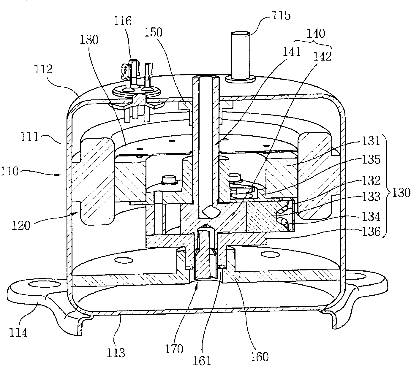
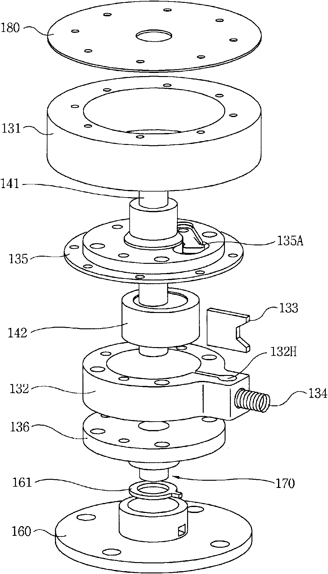
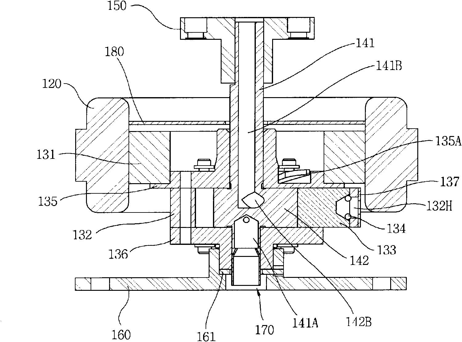
[0061] Such as Figure 1 to Figure 3 As shown, the first embodiment of the compressor according to the present invention includes: an airtight container 110; a stator 120, which is fixed in the airtight container 110; It can rotate and compress the refrigerant; the fixed part 140, which hangs the rotating part 130 on the outer peripheral surface, and at the same time, the upper and lower ends of the fixed shaft 141 are fixed to the airtight container 110 without moving; the upper shaft bracket 150, which is used When the upper end of the fixed shaft 141 is fixed on the inner side of the airtight container 110; the lower shaft bracket 160, while being separated from the lower end of the fixed shaft 141, is fixed on the inner side of the airtight container 110 so that the rotating part 130 is rotatably held by the airtight container 110. upper surface support. At this time, the motor mechanism unit that provides power by electric action includes the rotor 131 including the rota...


PUM


Abstract

The present invention relates to a compressor in which a rotary member (130) suspended on a stationary member (140) is rotated to compress the refrigerant. The rotary member (130) is suspended on a first portion of the stationary member and rotatably supported on a second portion of the stationary member, which is spaced a distance the first portion of the stationary member to thereby achieve structural stability, improve operational reliability and reduce vibrations. The components can be easily centered and assembled with excellent assembly characteristics. In addition, the mounting structure of an elastically-supported vane (133) is improved to ensure lubrication performance and operational reliability. Moreover, a mounting structure for a vane (234), which incorporates a roller(233), is improved to reduce vibration and prevent refrigerant leakage, which leads to high compression efficiency.

Description

technical field [0001] The present invention relates to a compressor in which a rotating member rotates while being suspended from a first fixed member while being supported on a second fixed member, and compresses refrigerant, and more particularly relates to a compressor capable of achieving structural stability and improving assemblability , and improve lubrication performance and work reliability, and reduce vibration while preventing refrigerant leakage, thereby improving the compression efficiency of the compressor. Background technique [0002] Generally speaking, a compressor (Compressor) is a mechanical device that receives power from a power generating device such as a motor or a turbine to compress air, refrigerant or other working gases to increase its pressure. It is widely used in refrigerators and Household appliances such as air conditioners or entire industries. [0003] The above-mentioned compressors are roughly divided into: Reciprocating compressor, whi...

Claims


Application Information

Patent Timeline
Patent Type & Authority Applications(China)
IPC IPC(8): F04C18/324F04C18/344F04C29/00
CPCF04C2240/10F04C18/3564F01C21/02F04C2230/603F04C29/0085F04C2240/60F04C2270/12F04C18/322F04C23/008F04C2240/40F04C29/0071F04C2240/30F04C29/023F04C2240/52F04C23/02
Inventor 李康旭李长祐史范东辛镇雄
Owner LG ELECTRONICS INC
Why Eureka
Try Eureka