
Method of producing electronic component mounting structure, and electronic component mounting structure

A technology for electronic component installation and electronic components, which is applied in the fields of printed circuit manufacturing, semiconductor/solid-state device manufacturing, electrical components, etc., and can solve problems such as difficult processes, increased weight, and decreased productivity

Inactive Publication Date: 2012-05-16
PANASONIC CORP
View PDF7 Cites 6 Cited by
  • Summary
  • Abstract
  • Description
  • Claims
  • Application Information

AI Technical Summary

Problems solved by technology

However, it is relatively difficult to form a film accurately in a separate process in a fine area such as the tip part or edge of the lead terminal, and the productivity decreases due to the increase in the process.
Furthermore, when another resin cured product is stacked, the weight increases accordingly, so it is not preferable from the viewpoint of weight reduction.

Method used


Image

  • Method of producing electronic component mounting structure, and electronic component mounting structure
  • Method of producing electronic component mounting structure, and electronic component mounting structure
  • Method of producing electronic component mounting structure, and electronic component mounting structure

Examples


Embodiment 1~8

[0056] (Preparation of liquid curable resin composition)

[0057] In this embodiment, as the liquid thermosetting resin, a solvent-free liquid silicone resin (trade name: SE-9187L manufactured by Dow Corning Toray Co., Ltd., hereinafter referred to as resin A), or a diluent (Dedicated diluent 904 (trade name)) Dissolved solid polyolefin (trade name manufactured by Chase Inc.: Humiseal 1B51NS, hereinafter referred to as resin B). In addition, in the resin B solution, the compounding ratio of the solid polyolefin and the diluent was 1:1 (weight ratio).

[0058] Furthermore, a solution of resin A or resin B was mixed with a foaming agent (4,4'-oxobis(benzenesulfonyl hydrazide); the gas generation temperature was about 170° C.) at the ratio shown in Table 1, and degassing was performed. Bubble treatment, thereby preparing a liquid curable resin composition. In addition, the content rate of the foaming agent in Table 1 is the weight ratio of the foaming agent with respect to the ...


PUM

PropertyMeasurementUnit
Thicknessaaaaaaaaaa

Abstract

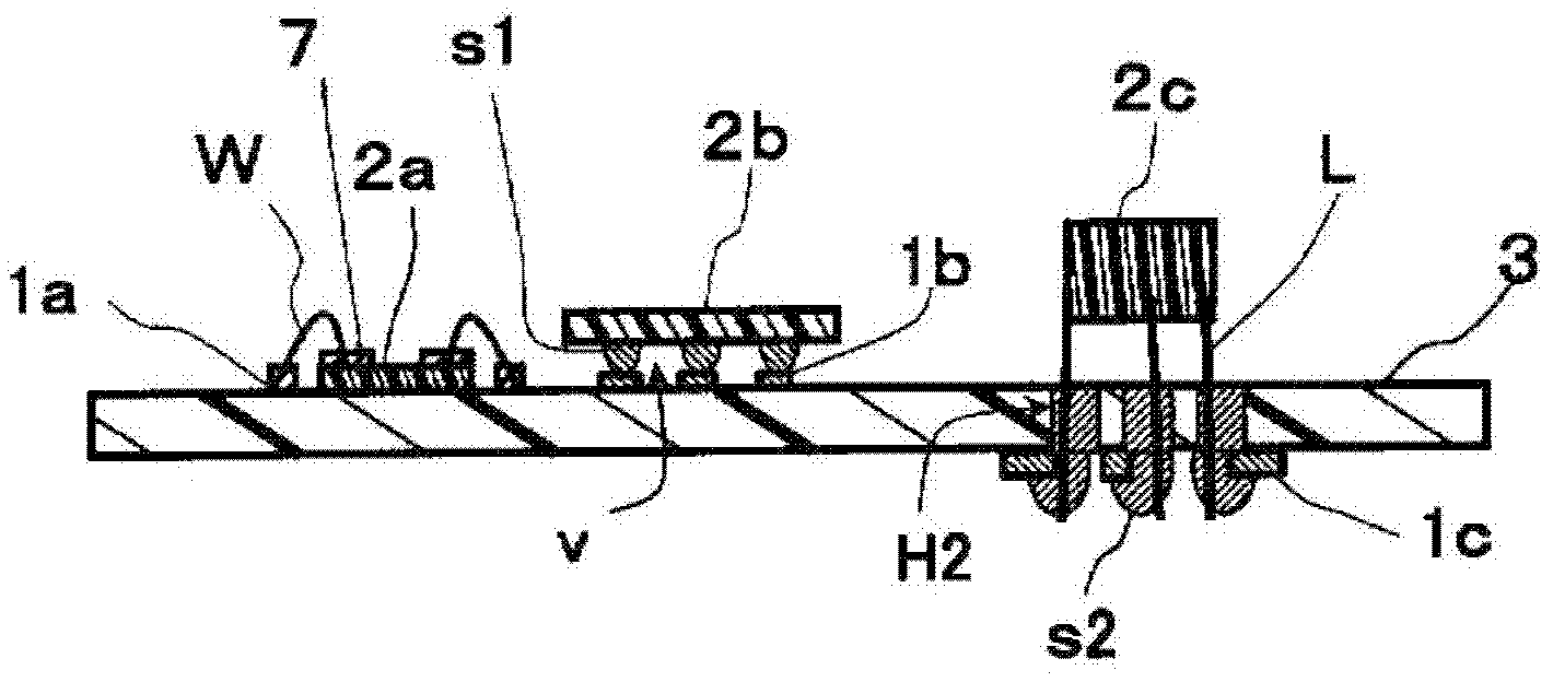
Disclosed is a method of producing an electronic component mounting structure, provided with a mounting step of mounting an electronic component on a circuit board by soldering terminals connected to the electronic component to electrodes formed on a circuit board surface, a coating step of coating a liquid state curable resin composition so as to cover the soldered section on the surface of the circuit board surface formed by soldering, said liquid state curable resin composition including a curable resin and a foaming agent, a curing step of forming a cured resin by curing the liquid state curable resin composition at a temperature lower than the temperature at which the foaming agent foams, and a foaming step which causes a foaming agent to foam by heating at least a portion of the cured resin.

Description

technical field [0001] The present invention relates to a method of manufacturing an electronic component mounting structure and an electronic component mounting structure. Specifically, it relates to a method for manufacturing an electronic component mounting structure capable of controlling the thickness of a cured resin that protects electronic components mounted on the surface of a circuit board. Background technique [0002] So far, in order to protect the electronic components mounted on the surface of the circuit board from contact with moisture, gas, dust, impact, etc., it is known that resin cured products such as epoxy resin, polyurethane, silicone resin, acrylic resin, etc. Coating method for covering electronic components. [0003] In addition, in order to reinforce the solder joint of the electronic component mounting structure formed by flip-chip bonding the electronic component on the surface of the circuit board, it is also known that there is a gap formed b...

Claims


Application Information

Patent Timeline
IPC IPC(8): H01L21/56H01L21/60H01L25/04H01L25/18H05K3/28
CPCH01L2924/14H01L2224/16H01L23/3121H05K3/284H01L2224/45144H01L2924/12041H01L21/56H01L2224/48091H05K2201/0116H05K2203/1105H01L2924/19043H01L2224/48227H01L2924/19041H01L24/16H01L24/48H01L2924/181H01L2924/00014H01L24/45H01L2924/00011H01L2924/00H01L2224/0401H01L2924/00012H01L2224/45015H01L2924/207
Inventor 小和田弘枝山口敦史松野行壮辻村英之
Owner PANASONIC CORP
Learn More