Fastener

A technology for fasteners and components, applied in the field of fasteners, can solve the problems of the rivet main body 61 and the pin 62 being difficult to engage, fall off, and shake.

Inactive Publication Date: 2013-12-25
NIFCO INC
View PDF2 Cites 0 Cited by
  • Summary
  • Abstract
  • Description
  • Claims
  • Application Information

AI Technical Summary

Problems solved by technology

Therefore, if the above-mentioned push rivet is used to fix the mounting member and the mounted member, and the engagement between the rivet body 61 and the pin 62 is released as described above, and the rivet body 61 and the pin 62 are used again, the rivet body 61 and the pin 62 will be damaged. It becomes difficult to engage due to fatigue and may fall off
In addition, the above-mentioned push rivet has the problem of rattling when the mounting member and the mounted member are thin.
In addition, when disengaging the above-mentioned mounting part and the mounted part using the above-mentioned push rivets, it is necessary to use a tool to forcibly release the engagement.

Method used


Image

  • Fastener
  • Fastener
  • Fastener

Examples


Embodiment Construction

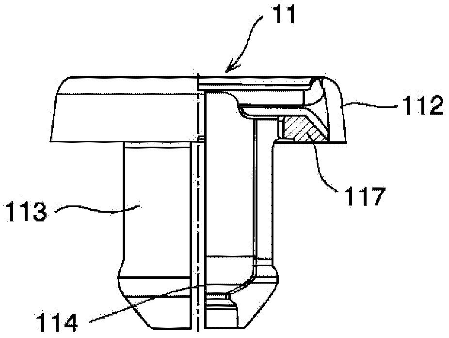
[0032] A fastener described below with reference to the drawings is an example of an embodiment of the present invention, and is inserted into mounting holes provided in a mounting member and a mounted member to fix the two to each other. More specifically, the above-mentioned fastener can be fixedly installed by inserting the male part into the female part installed in the mounting holes of the mounting part and the mounted part, and utilizing the above-mentioned male part to expand and set in the cylindrical part with the slit of the female part. Components and installed components so that they do not fall off each other. The female member has a flange portion provided with an insertion hole, a cylindrical portion integrally extending downward from the flange portion, and a substantially cross-shaped slit provided in the cylindrical portion. The slit formed in the shape of a cross groove is inserted into the leg portion and the sliding convex portion which will be described ...


PUM


Abstract

Disclosed is a fastener provided with a male member and a female member. The female member has: a flange part provided with an insertion hole; a cylindrical part that is formed from an elastically deformable member and extends downward from the flange part; and a slit provided in the cylindrical part. The male member has: a head; a shaft that extends downward from the head and, upon insertion into the cylindrical part of the female member, spreads said cylindrical part open; and a leg part provided with a latch part that, upon insertion into the cylindrical part of the female member, protrudes outward from the slit in the cylindrical part, and which expands outward from the bottom of the shaft to the top thereof. By inserting the cylindrical part of the female member into attachment holes in an attaching member and an attached member, and then pushing the male member into the insertion hole in the female member, the cylindrical part is spread outward, thus abutting against the rims of the attachment holes in the attaching member and the attached member, and fixing the attaching member and the attached member to each other; also, the latch part of the aforementioned leg part is made to protrude outward from the aforementioned slit, thus abutting against the rims of the attachment holes in the attaching member and the attached member, and fixing the attaching member and the attached member to each other.

Description

technical field [0001] The present invention relates to a fastener capable of mounting a mounting member and a mounted member in one operation, and capable of mounting without rattling and falling off regardless of the thickness of the mounting member and the mounted member. Furthermore, the present invention relates to a fastener that can be easily attached to the above-mentioned mounting member and mounted member, and can be detached without using a tool or the like at the time of release. Background technique [0002] A conventional fastener is described in, for example, the following Patent Document 1 (Japanese Utility Model Registration Application Publication No. Hei 6-40428). Figure 13 to Figure 15 is a diagram for explaining existing fasteners, Figure 13 and Figure 14 is a front view of an existing fastener partially cut away, Figure 15 With Figure 13 and Figure 14 The fastener shown is a top view of the same existing fastener. as existing fasteners are in...

Claims


Application Information

Patent Timeline
Patent Type & Authority Patents(China)
IPC IPC(8): F16B19/10
CPCF16B19/1081F16B21/086
Inventor 永山智著
Owner NIFCO INC
Why Eureka
Try Eureka