Treating equipment for waste containing sludge

A technology for treating equipment and waste, which is applied in water/sludge/sewage treatment, ceramic wastewater treatment, solid waste removal, etc., and can solve the problem of increased sewage sludge treatment volume, etc.

Active Publication Date: 2013-09-11
KAWASAKI HEAVY IND LTD +4
View PDF2 Cites 0 Cited by
  • Summary
  • Abstract
  • Description
  • Claims
  • Application Information

AI Technical Summary

Problems solved by technology

[0005] However, similar to the above-mentioned increase in demand for waste treatment, the amount of sewage sludge to be treated has also increased as the maintenance of sewage treatment plants has progressed.

Method used


Image

  • Treating equipment for waste containing sludge
  • Treating equipment for waste containing sludge
  • Treating equipment for waste containing sludge

Examples


Embodiment Construction

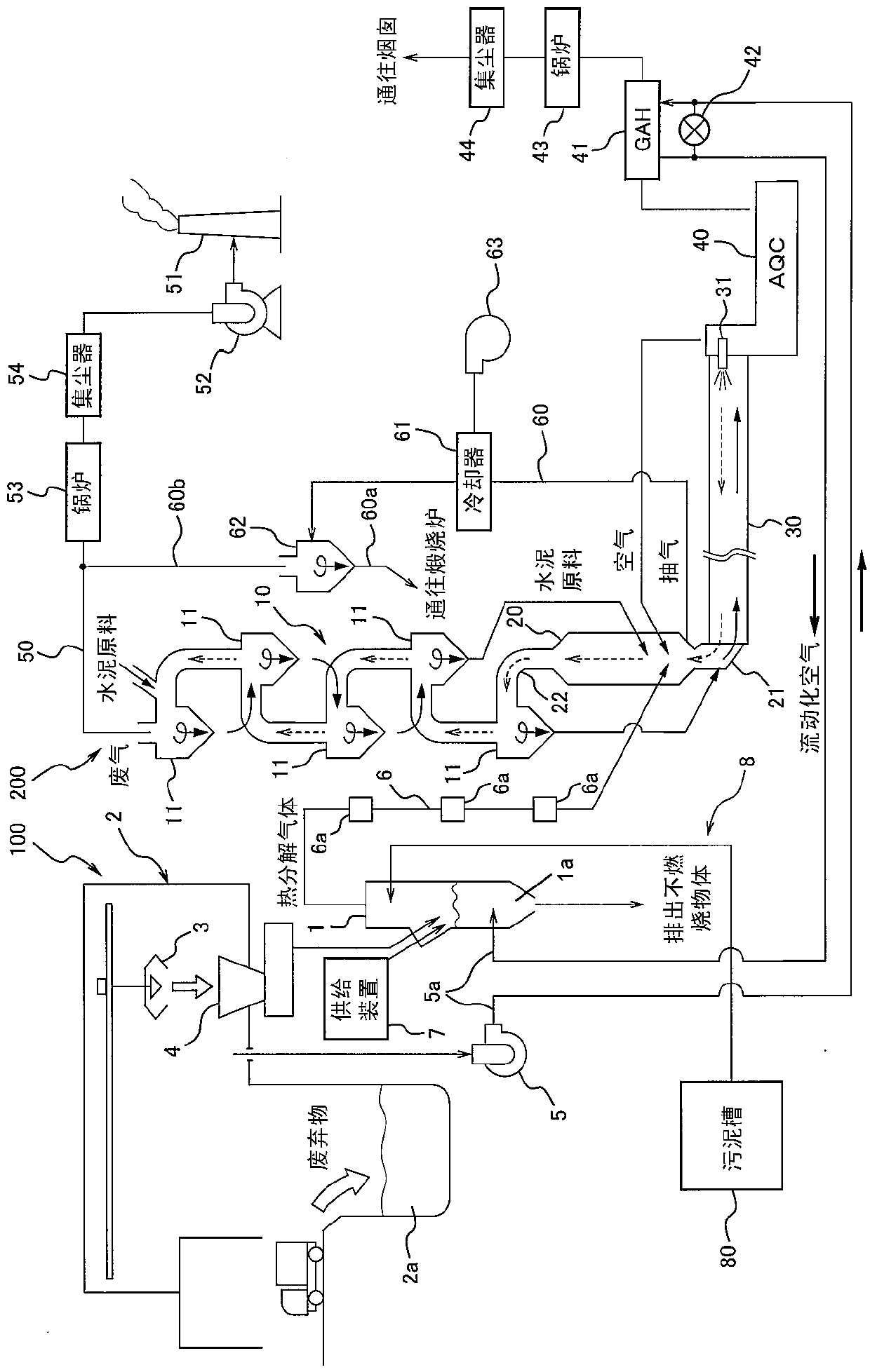
[0059] Preferred embodiments of the present invention will be described below with reference to the drawings. figure 1 It is an overall system diagram of the waste disposal facility 100 of the first embodiment and the cement manufacturing facility 200 installed adjacent thereto. figure 1 The waste treatment facility 100 shown on the left side of the center thermally decomposes waste in the gasification furnace 1 and uses the generated gas (pyrolysis gas) for mixed combustion in the cement firing process. The amount of the pyrolysis gas is, for example, 20,000 to 30,000 Nm 3 / h, and the exhaust gas volume of the cement manufacturing equipment shown in the figure 200 (for example, 300,000 Nm 3 / h) is much less, so the waste treatment plant 100 can be built next to an existing cement plant with little or no modification to the existing cement plant.

[0060] Waste Treatment Equipment

[0061] In the waste treatment facility 100, for example, waste from households, waste plasti...


PUM

PropertyMeasurementUnit
particle sizeaaaaaaaaaa

Abstract

In a fluidized bed type gasification furnace 1 for thermally decomposing wastes, a temperature of a fluidized bed 1a is maintained within a preferable range, even if the wastes containing a dewatered sludge having higher water content than the conventional wastes is processed. A waste treatment facility 100 is constructed in vicinity of a cement production facility 200. The apparatus comprises the fluidized bed type gasification furnace 1 for gasifying the wastes to generate a pyrolysis gas, and a gas transport line 6 for transporting the generated pyrolysis gas with entrained char and ash to a preheater 10 or a calciner 20 for cement. The apparatus also comprises a temperature elevating device such as a gas air heater 41 and the like, which elevates the temperature of the estimated value that is supplied to the gasification furnace 1 by utilizing waste heat of the cement production facility 200

Description

technical field [0001] The present invention relates to equipment for the hygienic disposal of waste using cement manufacturing equipment, and more particularly to the treatment of waste containing sludge with a high moisture content. Background technique [0002] In recent years, along with the improvement of living standards in developing countries, for example, there is an increasing need for sanitary disposal of waste, and an increase in the amount of waste incineration is also expected. However, there is also the problem that the construction of a general waste incinerator requires a large cost and a long construction period. Furthermore, in Japan there is still a shortage of landfill disposal sites for burying ash generated by calciners. When establishing a new waste disposal site, installation of ash melting furnaces and establishment of ash recycling methods are necessary conditions. [0003] In response to this, the inventors of the present application have develop...

Claims


Application Information

Patent Timeline
Patent Type & Authority Patents(China)
IPC IPC(8): C04B7/28C10J3/56
CPCC04B7/475C02F2103/12F23G5/0276C04B2290/20F23G5/46F23G2201/303C02F11/06F23G5/30F23G7/001F23G5/006C04B18/061B09B3/00F23G5/008F23G2206/201C04B7/4415C02F2209/02Y02E20/30Y02W10/40Y02P40/121C04B7/434C02F11/10
Inventor 林敏和井上英二渡边达也片畑正市谷升松内孝夫郭文叁李顺安何承发张长乐汪克春李朝晖
Owner KAWASAKI HEAVY IND LTD
Why Eureka
Try Eureka