
Power supply unit with pre-bias voltage control

A voltage control and power supply device technology, applied in the field of power supply, can solve the problems of output voltage distortion, PWM duty cycle and pre-biased output voltage have no corresponding relationship, enter discontinuous conduction mode, etc., and achieve the effect of improving reliability

Active Publication Date: 2016-01-20
HUAWEI DIGITAL POWER TECH CO LTD
View PDF5 Cites 0 Cited by
  • Summary
  • Abstract
  • Description
  • Claims
  • Application Information

AI Technical Summary

Problems solved by technology

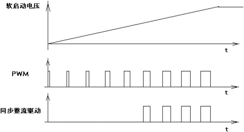
[0004] The control method of the pre-bias voltage in the prior art has the following problems: the capacitive load must be large enough, and the soft-start voltage rise time cannot be too long, if the soft-start voltage rise time is too long, it will enter the discontinuous conduction mode under light load ; There is no correspondence between the PWM duty cycle and the pre-biased output voltage
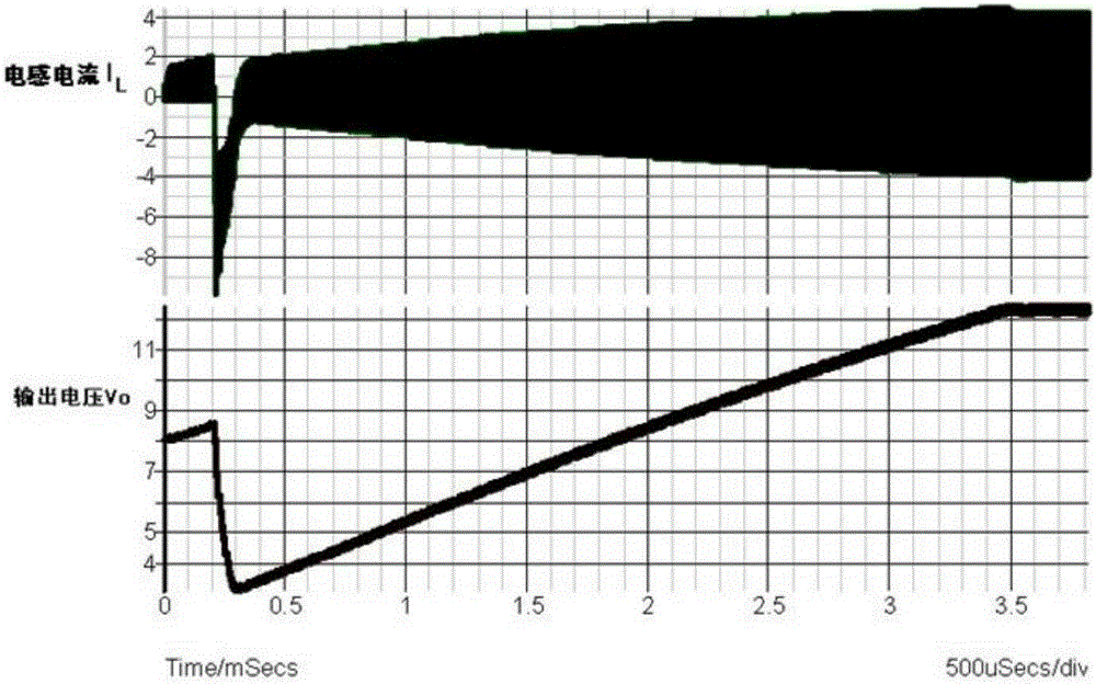
figure 2 Simulation waveform diagram for the prior art pre-bias voltage control method, such as figure 2 As shown, the reverse current of the inductor is very large, and the output voltage is severely distorted

Method used


Image

  • Power supply unit with pre-bias voltage control
  • Power supply unit with pre-bias voltage control
  • Power supply unit with pre-bias voltage control

Examples


Embodiment Construction

[0013] In order to express the technical solutions and advantages of the embodiments of the present invention more clearly, the technical solutions of the embodiments of the present invention will be further described in detail below with reference to the drawings and embodiments.

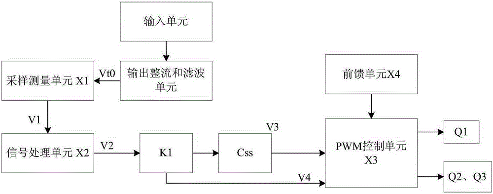
[0014] The principle of the embodiment of the present invention is that there is already a pre-bias voltage V on the output filter capacitor C1 in the output rectification and filter unit t0 , sampling measurement unit X1 to the pre-bias voltage V on the output filter capacitor C1 t0 sample and measure, and obtain a and pre-biased voltage V t0 Proportional to the sampling processing voltage V2, the sampling processing voltage V2 is processed by the linear operation of the signal processing unit X2 to obtain the processing voltage V3, that is, the linear operation in the signal processing unit is the processing voltage V3=K*V2+C, at this time, The first N-type transistor Q1 is turned on, and the pr...


PUM


Abstract

The embodiment of the invention relates to a power device with a pre-bias voltage control function. The power device comprises an input unit, an output rectifying and filtering unit, a sampling and measuring unit, a signal processing unit and a pulse width modulation (PWM) control unit, wherein the input unit is used for inputting an external voltage and transmitting the external voltage to the output rectifying and filtering unit; the output rectifying and filtering unit is used for rectifying and filtering a voltage in the input unit to generate an output voltage; the sampling and measuring unit is used for sampling a pre-bias voltage (Vt0) on an output filtering capacitor in the output rectifying and filtering unit, and processing the pre-bias voltage to obtain a sampling processing voltage (V1); the signal processing unit is used for performing linear operation on the sampling processing voltage to obtain a processing voltage (V2) which is linear with the pre-bias voltage; the PWM control unit is used for regulating the duty ratio of an input voltage according to the processing voltage (V2); and a voltage value of the converted input voltage with the regulated duty ratio is equal to the voltage value of the pre-bias voltage.

Description

technical field [0001] The invention relates to the field of power supplies, in particular to a power supply device with pre-bias voltage control in a power converter. Background technique [0002] At present, in order to improve the efficiency of electric energy conversion, MOSFET (metal-oxide-semiconductor) field effect transistors are used in the power converter instead of diodes to complete the synchronous rectification function, so as to improve the conversion efficiency of the power converter. MOSFET field effect transistor has the advantages of high input resistance, low conduction voltage, low power consumption, large dynamic range, and easy integration, which significantly improves the efficiency of power converters. At the same time, the use of MOSFET field effect transistors to complete the synchronous rectification function also brings new problems. Since the MOSFET field effect transistor is a bidirectional conduction device, the current on the filter inductor ...

Claims


Application Information

Patent Timeline
Patent Type & Authority Patents(China)
IPC IPC(8): H02M7/217H02M1/36
Inventor 刘旭君
Owner HUAWEI DIGITAL POWER TECH CO LTD
Learn More