
Tunnel lining self waterproof drainage system

A waterproof and drainage technology for tunnels, applied in tunnel lining, drainage, tunnels, etc., can solve unsolved tunnel leakage problems, affect lining and driving safety, reduce equipment service life, etc., achieve durable and reliable drainage characteristics, easy to clean The effect of silting and speeding up the construction period

Inactive Publication Date: 2012-05-02
中国市政工程西北设计研究院有限公司
View PDF5 Cites 58 Cited by
  • Summary
  • Abstract
  • Description
  • Claims
  • Application Information

AI Technical Summary

Problems solved by technology

Tunnel cracks, leakage, frost heave, water accumulation or icing will not only affect the lining and driving safety, but the humid environment will cause corrosion or short circuit of the equipment in the tunnel, which will reduce the service life of the equipment and affect the appearance of the tunnel
[0005] The current development trend is limited to improving the original system, such as using high-crack-resistant steel-brazed concrete or flexible fiber concrete to prevent cracks in the secondary lining; using chisels to remove the surface agglomeration of shotcrete, cutting off the base surface steel bars, pipe heads, etc. Methods such as sharp protrusions and mortar plastering the cover to prevent damage to the waterproof layer; measures such as using new materials and new techniques to improve the construction quality of the three joints to prevent leakage, etc. This method is limited to the waterproof and drainage professional to solve the problem of waterproof and drainage. Solve the problem of tunnel leakage

Method used


Image

  • Tunnel lining self waterproof drainage system
  • Tunnel lining self waterproof drainage system
  • Tunnel lining self waterproof drainage system

Examples


Embodiment Construction

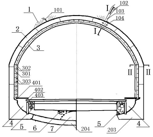
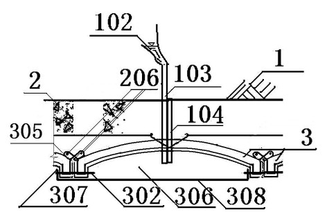
[0052] Such as Figure 1 to Figure 3 Shown: a tunnel lining self-proof drainage system, including surrounding rock bearing arch 1, cast-in-situ concrete main waterproof layer 2, precast concrete arch layer 3, longitudinal drainage ditch 4, arch layer construction joints and cast-in-situ concrete main waterproofing Staggered construction joints in each layer; it is characterized in that: at the position 102 of the concentrated water inflow and leakage point 102 in the soft surrounding rock, a movable drainage groove 308 is fixed under the prefabricated concrete arch layer 3, and the movable drainage groove 308 is connected with the inner surface of the prefabricated reinforced concrete arch 301. The concave surface forms a drainage space 306, and the side-by-side drainage spaces 306 arranged along the section of the tunnel form an active drainage ditch. The active drainage ditch is connected with the vertical drainage ditch 4 on both sides of the tunnel road surface, and the con...


PUM


Abstract

The invention relates to a tunnel lining self waterproof drainage system, which comprises a surrounding rock bearing arch, a cast-in-place cement main waterproof layer, a pre-cast cement arch sheet layer and longitudinal drainage channels. Arch sheet layer construction gaps and cast-in-place cement main waterproof layer construction gaps are interlaced. The tunnel lining self waterproof drainage system is characterized in that movable drainage grooves are fixedly arranged below the pre-cast cement arch sheet layer of centralized bursting water seepage points of loose surrounding rocks, and form arch sheet drainage spaces with an inwards concave surface of the pre-cast cement arch sheet layer, the parallel drainage spaces distributed along the section of a tunnel form a movable drainage channel, the longitudinal drainage channels are communicated and are arranged on two sides of the movable drainage channel and the pavement of the tunnel, pre-embedded water guiding pipes are arranged at the centralized bursting water seepage points, a water outlet end of each pre-embedded water guiding pipe is arranged on the inwards concave surface of the pre-cast cement arch sheet layer, and pre-embedded grouting pipes are arranged outside the pre-embedded water guiding pipes. The invention completely solves stubborn problems of the tunnel on cracking, seeping, frost heaving, ponding or freezing and the like on the premise of not arranging an interlayer waterproof layer and a hidden seepage water blind pipe drainage system, and the tunnel lining self waterproof drainage system disclosed by the invention has a simple structure and is convenient to construct.

Description

technical field [0001] The invention belongs to the technical field of waterproofing and drainage of tunnels and underground projects, and is suitable for tunnels, roadways, tunnels, tunnels, underground arched workshops, urban subways, basements of high-rise buildings, etc. Engineering waterproof and drainage facilities, specifically a tunnel lining self-waterproof and drainage system. Background technique [0002] At present, composite lining waterproof and drainage systems are widely used at home and abroad. see Figure 8 : In terms of waterproofing; in addition to the primary waterproofing layer 8 of spray anchor support and the main waterproofing layer 2 of cast-in-place concrete, a concealed interlayer waterproofing layer 7 is added, that is, it is generally installed in the whole hole between the primary supporting and the secondary lining Waterproof board, middle waterproof layer of non-woven fabric. In fact, due to the uneven thickness of the shotcrete supported b...

Claims


Application Information

Patent Timeline
IPC IPC(8): E21D11/10E21D11/08E21D11/38E21F16/02
Inventor 童景盛王胜利
Owner 中国市政工程西北设计研究院有限公司
Learn More