
Composite steel plate and manufacturing method for same

A technology of composite steel plate and manufacturing method, which is applied to manufacturing tools, chemical instruments and methods, non-electric welding equipment, etc., can solve the problems of stainless steel surface corrosion, liquid magnesium leakage, brittleness and peeling off of oxide film, etc., so as to reduce leakage and improve The effect of service life

Active Publication Date: 2012-05-02
太原钢铁(集团)有限公司
View PDF4 Cites 39 Cited by
  • Summary
  • Abstract
  • Description
  • Claims
  • Application Information

AI Technical Summary

Problems solved by technology

[0002] At present, in the smelting process of magnesium and magnesium alloys, in order to ensure the purity of magnesium and reduce the replacement reaction between magnesium and the alloy in steel, a composite steel plate for magnesium crucible is used, and Q245R is used as the lining. Hot stainless steel is used to improve the service life of the crucible, but sulfur oxides are released from the mold slag during the smelting process, and the stainless steel surface is corroded under the action of high temperature. Due to the poor adhesion between the oxide film and the substrate, the oxide film is brittle Shedding, resulting in thinning of the stainless steel, which loses its protective properties against the lining
Therefore, under the action of high temperature in the tank body during smelting, local corrosion occurs on the surface of the stainless steel, causing liquid magnesium to leak, causing great safety hazards to production, and shortening the service life of the tank body

Method used


Image

  • Composite steel plate and manufacturing method for same
  • Composite steel plate and manufacturing method for same
  • Composite steel plate and manufacturing method for same

Examples


Embodiment Construction

[0036] The specific embodiments of the composite steel plate and the manufacturing method thereof will be described in detail below in conjunction with the embodiments and the drawings, but the specific embodiments of the composite steel plate and the manufacturing method thereof are not limited to the following embodiments.

[0037] Composite steel plate example

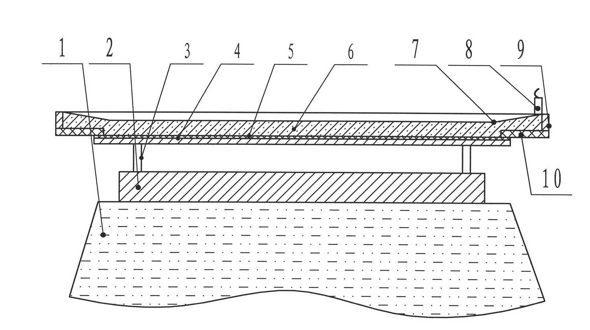
[0038] In this embodiment, the Q245R substrate in the national standard GB713 and the composite board are welded together. The length of the finished substrate is 6050mm, the width is 1050mm, and the thickness of the substrate is 26mm. The length and width of the composite board are equal to those of the substrate. The length is also 6050mm, the width is 1050mm, and the thickness of the composite plate is 4mm; it is characterized in that the composite plate is NAR-305B stainless steel of Japanese stainless steel standard JIS G 4305.

[0039] Manufacturing method embodiment

[0040] This example manufactures the composite st...


PUM

PropertyMeasurementUnit
thicknessaaaaaaaaaa
thicknessaaaaaaaaaa
lengthaaaaaaaaaa

Abstract

The invention relates to a composite steel plate and a manufacturing method for same. The composite steel plate comprises a Q245R base plate and an NAR-305B composite plate. The manufacturing method includes the successive steps: I, assembling the base plate and the composite plate in a matched manner; II, grinding a joint surface of the surface base plate so that surface roughness is no more than Ra 25 micrometers; III, laying explosion welding explosives on the composite plate, igniting the explosives, and welding the base plate together with the composite plate by means of explosion; IV, welding unwelded points by means of surface repair welding; V, performing heat treatment at the temperature of 900-920 DEG C and preserving heat for 15-20 minutes; VI, cutting the composite steel plate into the size of a finished composite steel plate; VII, testing mechanical properties of the composite steel plate according to GB / T6396-2008; VIII, performing 100% ultrasonic flaw detection for the composite steel plate according to NB / T47002-2009; and IX, grinding the surface of the composite steel plate so that surface roughness is no more than Ra 2 micrometers. The composite steel plate manufactured by the manufacturing method for the composite steel plate is corrosion-resistant and long in service life.

Description

Technical field [0001] The invention relates to a composite steel plate and a manufacturing method thereof, in particular to a composite steel plate for a magnesium crucible and a manufacturing method thereof. Background technique [0002] At present, in the smelting process of magnesium and magnesium alloys, in order to ensure the purity of magnesium and reduce the substitution reaction between magnesium and the alloy in steel, a composite steel plate for magnesium crucibles is used, and Q245R is used as the lining. Hot stainless steel can increase the service life of the crucible, but sulfur oxides are released from the mold slag during the smelting process, and the surface of the stainless steel is corroded under the action of high temperature. Due to the poor adhesion between the oxide film and the substrate, the oxide film is brittle Falling off causes the thinning of the stainless steel and loses its protection to the lining. Therefore, under the action of high temperature...

Claims


Application Information

Patent Timeline
Patent Type & Authority Applications(China)
IPC IPC(8): B23P15/00B23K20/08B32B15/01B32B15/18
Inventor 卫世杰
Owner 太原钢铁(集团)有限公司
Learn More