
Semiautomatic meter reading device and meter reading method thereof

A semi-automatic and equipment technology, applied in signal transmission systems, instruments, electrical signal transmission systems, etc., can solve problems such as difficulty in implementing centralized reading systems, and achieve the goal of reducing construction difficulty, system operation energy consumption, and equipment investment costs. Effect

Active Publication Date: 2014-06-25
QINGDAO IESLAB ELECTRONICS CO LTD
View PDF3 Cites 0 Cited by
  • Summary
  • Abstract
  • Description
  • Claims
  • Application Information

AI Technical Summary

Problems solved by technology

However, most residential quarters do not have grounding wires installed in each building unit, which causes great difficulties in the implementation of centralized copying system construction.

Method used


Image

  • Semiautomatic meter reading device and meter reading method thereof
  • Semiautomatic meter reading device and meter reading method thereof
  • Semiautomatic meter reading device and meter reading method thereof

Examples


Embodiment 1

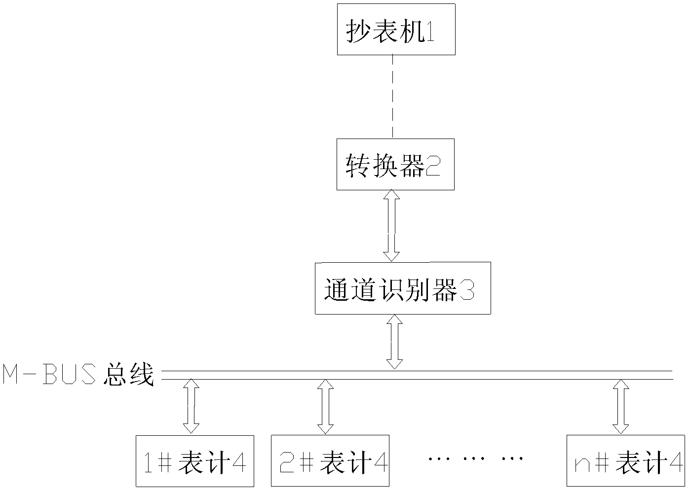
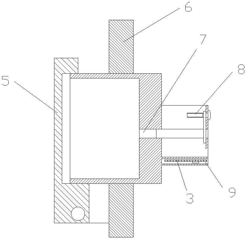
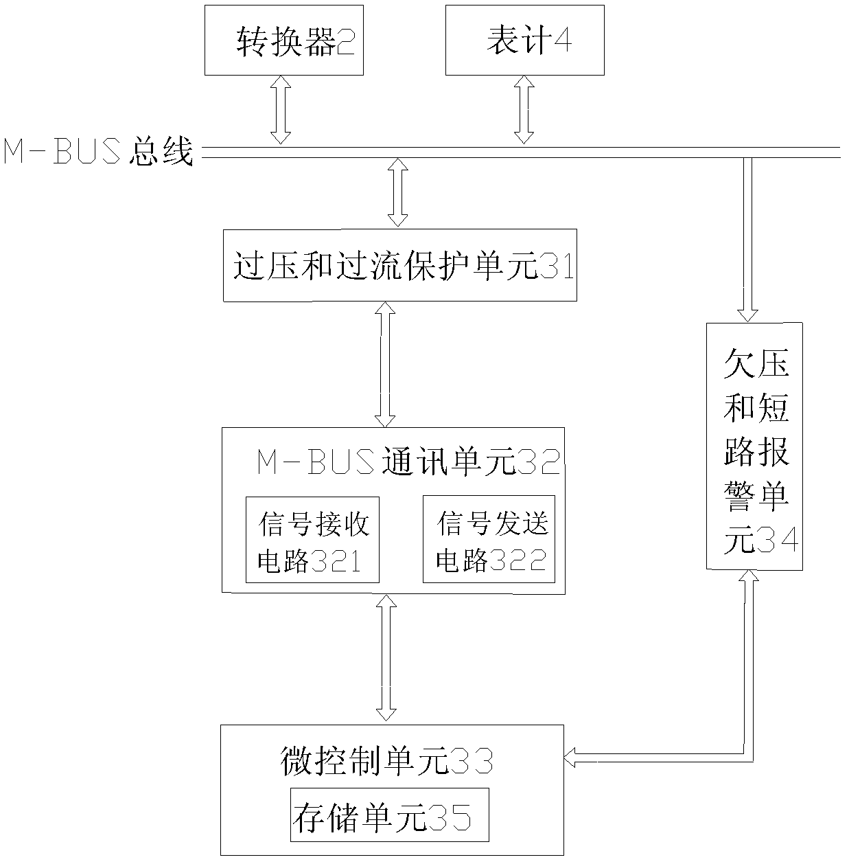
[0032]A semi-automatic meter reading device, as shown in the figure, includes n meters 4 (which can be electric meters, gas meters, water meters or heat meters), a socket 6, a converter 2 and a meter reading machine 1, and the front end of the socket 6 There is a socket 7 and an outer cover 5, and a cavity 9 is provided at the rear end for installing the channel identifier 3, and the rear end of the socket 6 is also provided with a terminal 8 connected to the socket 7 for connecting the channel identifier 3 and the external M-BUS bus, the M-BUS bus is connected to each meter 4, and the socket connects the channel identifier and each meter. The channel recognizer 3 includes a first micro-control unit 33, an M-BUS communication unit 32, an overvoltage and over-current protection unit 31, and an undervoltage and short-circuit alarm unit 34. The first micro-control unit 33 is built-in for generating identification The program of the code and the meter address list is also provided...

Embodiment 2

[0034] The meter reading method using the above-mentioned semi-automatic meter reading device comprises the following steps:

[0035] (1) The meter reader enters the unit building where the above socket is installed. The socket has been connected to all the meters of the unit through the M-BUS bus, inserts the pin of the converter into the socket of the socket, and turns on the power switch of the converter , to supply power to the channel identifier in the socket and the meter of this unit;

[0036] (2) Operate the meter reading machine, start the channel identifier to automatically inspect the meter addresses within the specified range, and generate an address list, which is stored in the storage unit;

[0037] (3) Operate the meter reading machine to obtain the address list generated by the channel identifier as the meter address database during meter reading;

[0038] (4) Operate the meter reading machine to obtain the current readings of the meters contained in the addre...


PUM


Abstract

The invention relates to a meter reading device and a meter reading method, in particular to a semiautomatic meter reading device and a meter reading method thereof. The meter reading device comprises a meter, a converter and a meter reading machine, and also comprises a socket for the converter to be plugged, wherein the socket is connected with the meter in a M-BUS bus way, and the converter is wirelessly connected with the meter reading machine; a channel recognizer is installed inside the socket, and the channel recognizer is connected with the socket through a conducting wire; the channel recognizer comprises a micro-control unit, an identity identifier and a program for automatically generating a meter address list are embedded in the micro-control unit, and a memory unit for storing the identifier and the meter address list is also arranged inside the micro-control unit. When the meter is read, pins of the converter are connected with the socket, and an address list is generated by the channel recognizer so as to read the meter. Due to the adoption of the meter reading way, the problem that the meter reading device is difficult to acquire electricity and is difficultly grounded can be solved, the system operation energy consumption can be reduced, the size of the socket is small, and the installation space is saved.

Description

technical field [0001] The invention relates to a meter reading device and a meter reading method, in particular to a semi-automatic meter reading device and a meter reading method. Background technique [0002] With the development of science and technology, centralized meter reading technology has also been developed rapidly. Centralized meter reading can read the information of electric meters, water meters, gas meters, heat meters and other meters of multiple users at one time, and the meter reading is fast and convenient. At present, the commonly used meter reading technology in electric power is the automatic meter reading method. The collector installed in the building is connected to the user's meter by cable. One or several concentrators are installed in each station area. Power line carrier or RF wireless communication, the concentrator summarizes and processes the meter data under its jurisdiction and uploads it to the main station of the data center through GPRS ...

Claims


Application Information

Patent Timeline
Patent Type & Authority Patents(China)
IPC IPC(8): G08C19/00G08C17/02
Inventor 张德霞韩飞舟冯建科于洪永曲延河
Owner QINGDAO IESLAB ELECTRONICS CO LTD
Learn More