
Unpolarized interference high-sensitivity photonic crystal fiber temperature sensor and manufacturing method thereof

A photonic crystal fiber and temperature sensor technology, applied in the field of optoelectronics, can solve the problems of low temperature sensitivity, inability to use temperature sensors, and limit the application of photonic crystal fibers, and achieve the effects of high temperature sensitivity and simple optical path.

Inactive Publication Date: 2012-04-18
NANJING UNIV
View PDF3 Cites 26 Cited by
  • Summary
  • Abstract
  • Description
  • Claims
  • Application Information

AI Technical Summary

Problems solved by technology

However, since the photonic crystal fiber is composed of a single material and its thermo-optic coefficient is very small, its temperature sensitivity is very low. Generally, the temperature sensitivity of the non-polarization interference device based on photonic crystal fiber is less than 10pm / ℃, so it cannot be used to prepare Temperature sensor, which also limits the application of photonic crystal fiber to a certain extent

Method used


Image

  • Unpolarized interference high-sensitivity photonic crystal fiber temperature sensor and manufacturing method thereof
  • Unpolarized interference high-sensitivity photonic crystal fiber temperature sensor and manufacturing method thereof
  • Unpolarized interference high-sensitivity photonic crystal fiber temperature sensor and manufacturing method thereof

Examples


Embodiment Construction

[0023] The present invention will be further described below in conjunction with the accompanying drawings and specific embodiments, so that the features of the present invention can be clearly demonstrated.

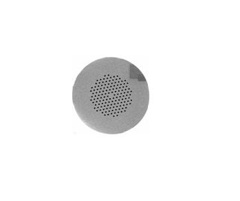
[0024] figure 1 is the light path diagram of the present invention, wherein the broadband light source emits light in the C+L band (1525-1610nm). In the experiment, one end of the LMA-8 photonic crystal fiber was first cut flat with a fiber cutter, and then the flat photonic crystal fiber was immersed in a liquid with a high thermal-optic coefficient (isopropanol, acetone, PX or tartaric acid, have a considerable effect) for a minute or so, and then splice it with a standard single-mode fiber. Then cut the other end of the fused photonic crystal fiber flat, and then weld it with the standard single-mode fiber. When welding (using commercially available experimental welding equipment), it is necessary to reasonably control the welding time, discharge intensity and other ...


PUM


Abstract

The invention provides an unpolarized interference high-sensitivity photonic crystal fiber temperature sensor which comprises a small section of photonic crystal fiber and single mode fibers which are connected, wherein the photonic crystal fiber is arranged in the middle section and filled with high thermo-optical coefficient liquid, the single mode fibers are arranged at two ends and the high thermo-optical coefficient liquid does not contact with the outside directly; the used photonic crystal fiber comprises a solid core and an air cladding, the high thermo-optical coefficient liquid is sealed in the air cladding of the photonic crystal fiber and has a length between several millimeters and dozens of millimeters. According to the manufacturing method of the unpolarized interference high-sensitivity photonic crystal fiber temperature sensor, common single mode fibers are used for input / output light guide of the fiber temperature sensor, a small section of photonic crystal fiber filled with the high thermo-optical coefficient liquid is welded between the single mode fibers by adopting an arc welding method, the high thermo-optical coefficient liquid is sealed in the photonic crystal fiber and does not contact with the outside. The unpolarized interference high-sensitivity photonic crystal fiber temperature sensor has novel design, is feasible to manufacture, and has a wide application prospect in the fields such as fiber sensing and the like. At present, temperature sensitivity obtained by using isopropanol is 103.7pm / DEG C.

Description

technical field [0001] The invention relates to the field of optoelectronic technology, in particular to the research and preparation of optical fiber sensors. More specifically, a high-sensitivity photonic crystal fiber interference temperature sensor is prepared by pouring a liquid with a high thermo-optic coefficient into the photonic crystal fiber and then fusing it with a single-mode fiber. Background technique [0002] Optical fiber sensing is a new technology that came out in the 1970s. It is a sensing technology that uses light as the information carrier and optical fiber as the information transmission medium. Compared with traditional sensors, optical fiber sensors have the advantages of small size, light weight, no electromagnetic interference, and high sensitivity. Since the advent of low-loss optical fibers in the 1970s, it has gradually become one of the research and development directions of new-generation sensors. A very good application prospect. In recent...

Claims


Application Information

Patent Timeline
IPC IPC(8): G01K11/32G02B6/02G02B6/032
Inventor 徐飞邱孙杰陆延青胡伟
Owner NANJING UNIV
Learn More