
Carbon calcinations rotary kiln secondary wind pipe installation structure and installation method

A secondary air duct and installation structure technology, applied in the direction of rotary drum furnace, furnace, lighting and heating equipment, etc., can solve the problem that the protective layer of refractory castable cannot be laid in advance, the installation structure of the secondary air duct is unreasonable, and maintenance personnel operate Harsh environment and other problems, to achieve the effect of health protection, avoid a large drop in temperature, and prevent scald accidents

Inactive Publication Date: 2012-04-18
SHENYANG ALUMINIUM MAGNESIUM INSTITUTE
View PDF6 Cites 7 Cited by
  • Summary
  • Abstract
  • Description
  • Claims
  • Application Information

AI Technical Summary

Problems solved by technology

[0004] In order to solve the above technical problems, the present invention provides a carbon calcination rotary kiln secondary air pipe installation structure and installation method. Refractory castable protective layer, long cooling time and large cooling range during secondary air duct maintenance, harsh operating environment for maintenance personnel, high risk of high temperature, large damage to kiln lining, short service life, etc.

Method used


Image

  • Carbon calcinations rotary kiln secondary wind pipe installation structure and installation method
  • Carbon calcinations rotary kiln secondary wind pipe installation structure and installation method
  • Carbon calcinations rotary kiln secondary wind pipe installation structure and installation method

Examples


Embodiment Construction

[0028] The embodiments of the present invention will be described in detail below in conjunction with the accompanying drawings, but the protection scope of the present invention is not limited by the embodiments.

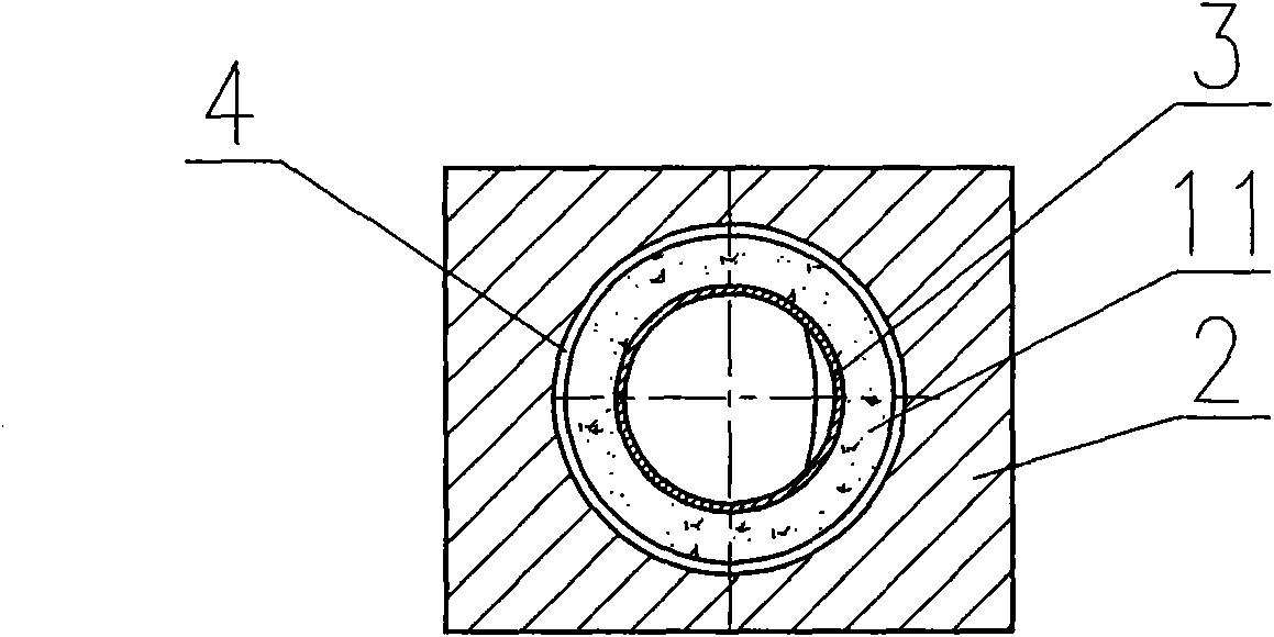
[0029] Such as Figure 1-3 As shown, the carbon calcination rotary kiln secondary air duct installation structure of the present invention includes a rotary kiln shell 1 and a kiln lining 2, and the rotary kiln shell 1 and the kiln lining 2 are provided with an installation hole 4, and the installation hole 4 is provided with There is a secondary air duct 3 with a refractory castable protective layer 11, and the end of the secondary air duct 3 outside the installation hole 4 is provided with an end flange 9, and the end flange 9 is connected to the fan, and the secondary air duct 3 Heat-resistant steel pipe is used, and the sealing sleeve 5 is put on the secondary air pipe 3 outside the rotary kiln cylinder 1. The sealing sleeve 5 is welded on the kiln outer skin, ...


PUM


Abstract

The invention relates to a carbon calcinations rotary kiln in the production field of an aluminum anode, in particular to a carbon calcinations rotary kiln secondary wind pipe installation structure and installation method. The carbon calcinations rotary kiln secondary wind pipe installation structure comprises a rotary kiln cylinder body and a kiln liner, and is characterized in that: the rotarykiln cylinder body and the kiln liner are respectively provided with an installation hole, a secondary wind pipe with a fire-resisting pouring material protection layer is arranged inside the installation hole, a sealing sleeve is sleeved on the secondary wind pipe at the outer side of the rotary kiln cylinder body, the upper end of the sealing sleeve is provided with an upper end flange with a suspension overturning bolt, the middle-upper part of the secondary wind pipe is provided with a fixed flange which is fixedly arranged on the upper end flange, and flexible heat-resisting sealing stuffing is arranged between the sealing sleeve and the secondary wind pipe. The fire-resisting pouring material protection layer which is coated outside the secondary wind pipe can be laid in a safe and wide field outside the kiln, so the construction quality of the pouring material protection layer can be guaranteed. Due to the adoption of the installation structure and the installation method, the repairing time can be greatly shortened, the calcinations production capacity of a rotary kiln can be improved, the structure is simple, economical performance and practicability can be realized, and easiness for implementation can be realized.

Description

technical field [0001] The invention relates to a carbon calcination rotary kiln in the field of aluminum anode production, in particular to a carbon calcination rotary kiln secondary air pipe installation structure and installation method. Background technique [0002] The current secondary air duct of the carbon calcination rotary kiln is to extend the metal tube into the kiln tube and fix it outside the kiln tube. The construction personnel enter the kiln tube and weld a certain number of anchors on the outer wall of the metal tube. , and then apply a layer of refractory castable about 50mm thick to resist the high temperature of about 1300 ℃ in the kiln. [0003] During the operation of the carbon calcination rotary kiln, due to the large temperature gradient of the secondary air duct and its castable protective layer, which can reach more than 20°C / mm, the refractory castable on the secondary air duct is easily peeled off, making it difficult to penetrate into the kiln....

Claims


Application Information

Patent Timeline
Patent Type & Authority Applications(China)
IPC IPC(8): F27B7/36
Inventor 吕博王忠心于国友崔银河张晓新高广轶
Owner SHENYANG ALUMINIUM MAGNESIUM INSTITUTE
Learn More